Audi Q7: Drive Axle, Disassembling and Assembling
Drive Axle, Disassembling and Assembling, Triple Roller Joint AAR 3300i
Special tools and workshop equipment required
- Press Plate -VW401-
- Press Plate -VW402-
- Press Piece - Rod -VW408A-
- Press Piece - Rod -VW411-
- Press Piece - 37mm -VW416B-
- Press Piece - Multiple Use -VW447H-
- Slide Hammer Set -VW771-
- Tripod Joint Tool -T10065-
- Triple Roller Assembly Tool -T40018-
- Pneumatic Hydraulic Press -VAS6654-, not illustrated
- Commercially available locking ring pliers.
Disassembling
- Clamp the drive axle horizontally in a vise with protective covers.
 Note
Note
Make sure that drive axle is not damaged.
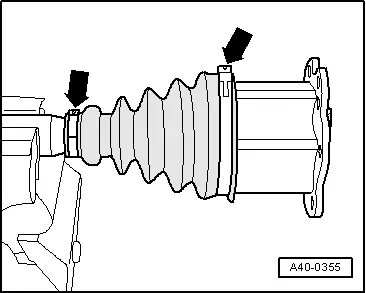
- Open clamps -arrows-.
- Slide back protective boot.
 Caution
Risk of noises when driving due to a changed installation position.
For reinstallation mark the installation position of the joint to the drive axle using for example a waterproof marker.

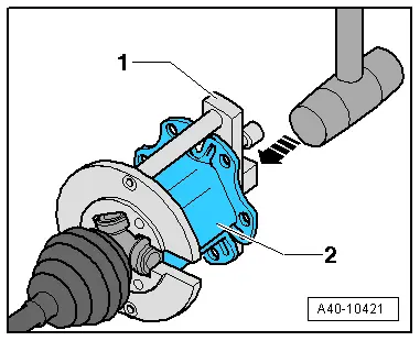
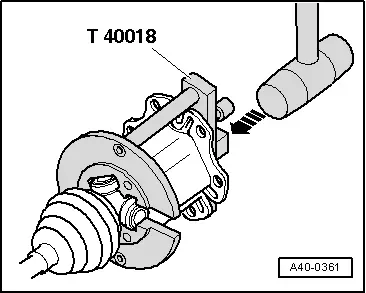
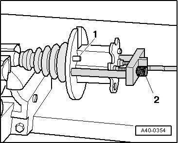
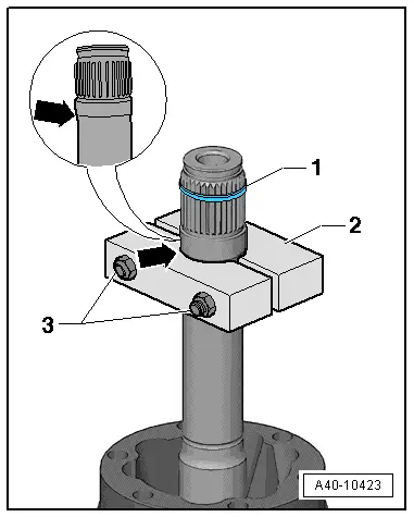
- Guide the Triple Roller Assembly Tool -T40018- behind the joint.
- The guide pins -1- must contact the outer joint.
- Move the Triple Roller Assembly Tool -T40018- to the joint until stop by turning knurled bolts -2-.
 Note
Note
- Secure the joint without play in the Triple Roller Assembly Tool -T40018-.
- Only tighten the knurled bolts hand tight.

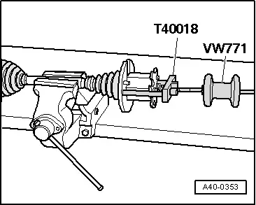
- Install the Slide Hammer Set -VW771- in the Triple Roller Assembly Tool -T40018-.
- Remove the joint horizontally with the Slide Hammer Set -VW771-.
- Leave the joint in the Triple Roller Assembly Tool -T40018-.
 Caution
Risk of noises when driving due to a changed installation position.
For reinstallation mark the installation position of the drive axle -1- to the triple roller star -2- using for example a waterproof marker.
- Remove grease with lint-free cloth.
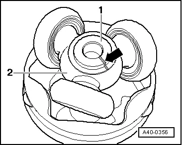
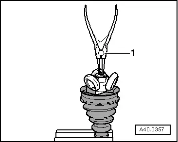
- Remove the circlip with locking ring pliers -1-.

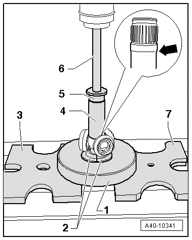
- Mount the special tools as shown.
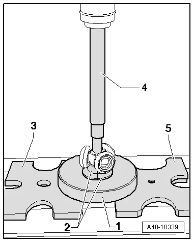
1 - Assembly Tool -T10065/1-
2 - Triple Roller Assembly Tool -T10065/5+/6-
3 - Press Plate -VW401-
4 - Press Piece - Rod -VW408A-
5 - Press Plate -VW402-
- Triple Roller Assembly Tool -T10065/5+/6- - must touch the triple roller star base
- The Triple Roller Assembly Tool -T10065/5+/6- must not touch the rollers; move the rollers to the side if necessary.
- Press the triple roller star off the drive shaft.
- Remove the protective boot.
- Remove the grease on the shaft splines.
- Check the roller body and ball cage for wear.
- Clean drive axle and housing.
Assembling
- Slide on the small clamp with the CV boot.
- Position the CV boot between the -arrows- on the drive axle.
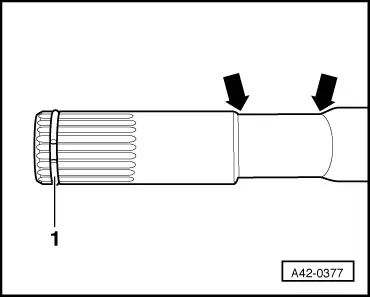
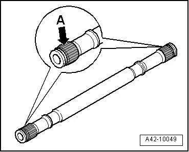
- Before installing the joint or triple roller star, splines -arrow A- must be lightly coated with grease used in joint.
- Place triple roller star on shaft according to mark and drive on until impact.

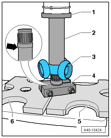
- Mount the special tools as shown.
1 - Assembly Tool -T10065/1-
2 - Triple Roller Assembly Tool -T10065/5+/6-
3 - Press Plate -VW401-
4 - Press Piece - 37mm -VW416B-
5 - Press Piece - Multiple Use -VW447H-
6 - Press Piece - Rod -VW411-
7 - Press Plate -VW402-
- Triple Roller Assembly Tool -T10065/5+/6- - must attach to the bead at the bottom of the drive axle -arrow-.
- The Triple Roller Assembly Tool -T10065/5+/6- must not touch the rollers; move the rollers to the side if necessary.
- Install the circlip with locking ring pliers -1-.
- Circlip must engage audibly, triple roller star must lie against circlip with no gap.
- Press the drive axle grease from the repair kit into the rear side of the triple roller joint.
- Lightly grease the roller body.

- Press the joint over the triple roller star using a plastic hammer in direction of -arrow-. At the same time make sure roller body does not tilt!
- Press remaining quantity of grease in protective boot.
- Make sure the protective boot is seated on the joint correctly.
- The CV boot must fit in the groove and on joint contour.
- Triple roller joint clamps, installing and tensioning. Refer to → Chapter "Clamp on Triple Roller Joint and Outer Joint, Tensioning".
Drive Axle, Disassembling and Assembling, Triple Roller Joint AAR 3700i
Special tools and workshop equipment required
- Press Plate -VW401-
- Press Plate -VW402-
- Press Piece - Rod -VW409-
- Press Piece - Multiple Use -VW412-
- Press Piece - 37mm -VW416B-
- CV Joint Press Sleeve -VW522-
- Slide Hammer Set -VW771-
- Press Block -40-204A-
- Triple Roller Assembly Tool -T40236-
- Pneumatic Hydraulic Press -VAS6654-, not illustrated
- Commercially available locking ring pliers.
Disassembling
- Clamp the drive axle horizontally in a vise with protective covers.
 Note
Note
Make sure that drive axle is not damaged.
- Open clamps -arrows-.
- Slide back protective boot.
 Caution
Risk of noises when driving due to a changed installation position.
For reinstallation mark the installation position of the joint to the drive axle using for example a waterproof marker.
- Guide the Triple Roller Assembly Tool -T40236- behind the joint.
- The guide pins -1- must contact the outer joint.
- Move the Triple Roller Assembly Tool -T40236- to the joint until stop by turning knurled bolts -2-.
 Note
Note
- Secure the joint without play in the Triple Roller Assembly Tool -T40236-.
- Only tighten the knurled bolts hand tight.
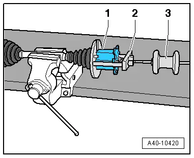
- Install the Slide Hammer Set -VW771--3- in the Triple Roller Assembly Tool -T40236--2-.
- Remove the joint -1- horizontally with the Slide Hammer Set -VW771-.
- Leave the joint in the Triple Roller Assembly Tool -T40236-.
 Caution
Risk of noises when driving due to a changed installation position.
For reinstallation mark the installation position of the drive axle -1- to the triple roller star -2- using for example a waterproof marker -arrow-.
- Remove grease with lint-free cloth.

- Remove the circlip with locking ring pliers -1-.

- Mount the special tools as shown.
1 - Press Piece - Rod -VW409-
2 - Triple roller star
3 - CV Joint Press Sleeve -VW522-
4 - Press Plate -VW401-
5 - Press Plate -VW402-
- The CV Joint Press Sleeve -VW522- must contact the locking ring -arrow-. The locking ring is removed together with the triple roller star from the drive axle.
- The CV Joint Press Sleeve -VW522- must not touch the rollers; move the rollers to the side if necessary.
- Press the triple roller star off the drive shaft.
- Remove the protective boot.
- Remove the grease on the shaft splines.
- Check the roller body and ball cage for wear.
- Clean drive axle and housing.
Assembling
- Slide on the small clamp with the CV boot.
- Position the CV boot between the -arrows- on the drive axle.

- Before installing the joint or triple roller star, splines -arrow A- must be lightly coated with grease used in joint.
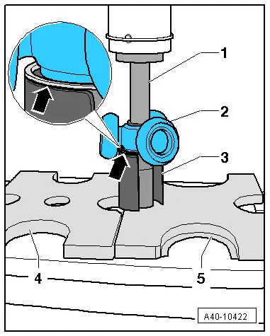
- Install the Press Block - 40-204A--2- as shown.
- The Press Block -40-204A- - must attach to the bead at the bottom of the drive axle -arrow-.
- Tighten the nuts -3- hand tight.
- Insert the new circlip -1- to center of splines
- Place triple roller star on shaft according to mark and drive on until impact.
- Mount the special tools as shown.
1 - Press Piece - Multiple Use -VW412-
2 - Press Piece - 37mm -VW416B-
3 - Triple roller star
4 - Press Block -40-204A-
5 - Press Plate -VW402-
6 - Press Plate -VW401-
- The Press Piece - 37mm -VW416B- larger internal diameter points to the triple roller star.
- The Press Block -40-204A- - must attach to the bead at the bottom of the drive axle -arrow-.
- The Press Block -40-204A- must not touch the rollers; move the rollers to the side if necessary.
- Install the triple roller star.
- Circlip must engage audibly, triple roller star must lie against circlip with no gap.
- Install the circlip with locking ring pliers -1-.
- Press the drive axle grease from the repair kit into the rear side of the triple roller joint.
- Lightly grease the roller body.
- Press the joint -2- over the triple roller star using a plastic hammer in direction of -arrow-. At the same time make sure roller body does not tilt!
1 - Triple Roller Assembly Tool -T40236-
- Press remaining quantity of grease in protective boot.
- Make sure the protective boot is seated on the joint correctly.
- The CV boot must fit in the groove and on joint contour.
- Triple roller joint clamp, installing and tensioning. Refer to → Chapter "Clamp on Triple Roller Joint and Outer Joint, Tensioning".