
Audi Q7: Glove Compartment Lamp -W6-, Removing and Installing
Removing
- Turn the light switch to position "0".
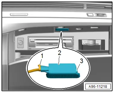
- Press the tab -3- in using a flat-head screwdriver and pry out the glove compartment lamp -2-.
- Disconnect the connector -1-.
Installing
Install in the reverse order of removal while noting the following:
- Insert the glove compartment lamp into the opening and engage on the opposite side.
Left and Right Front Footwell Lamp -K268-/-K269-, Removing and Installing
Removing
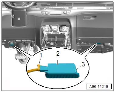
- Press the tab -3- in using a flat-head screwdriver and pry out the footwell lamp -2-.
- Disconnect the connector -1-.
Installing
Install in the reverse order of removal while noting the following:
- The entire footwell lamp must be replaced if an LED is faulty.
- Insert the footwell lamp into the opening and engage on the opposite side.
Central Locking -Safe- Indicator Lamp -K133-, Removing and Installing
Removing
- Remove the front door trim panel. Refer to → Body Interior; Rep. Gr.70; Front Door Trim Panels; Front Door Trim Panel, Removing and Installing.
- Release the clips in direction of -arrows-.
- Remove the central locking LED -1- downward and out of the door trim panel -2-.

Installing
Install in the reverse order of removal while noting the following:
TIP
The new Central Locking -Safe- Indicator Lamp -K133- must be connected with the door trim panel wiring harness.
- Disconnect the wire and connect it with the new wire for the Central Locking -SAFE- Indicator Lamp -K133-. Refer to → Electrical Equipment General Information; Rep. Gr.97; Wiring Harness and Connector Repairs; Wiring Harnesses, Repairing.
Front Interior Door Handle Illumination Lamp, Removing and Installing
Removing
- Remove the front door trim panel. Refer to → Body Interior; Rep. Gr.70; Front Door Trim Panels; Front Door Trim Panel, Removing and Installing.
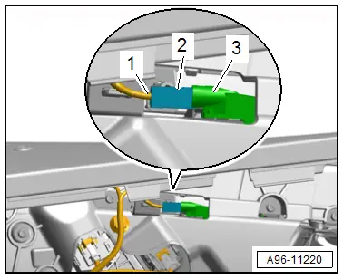
- Turn the bulb socket -2- to the left and remove it from the lighting strip -3-.
- Disconnect the connector -1-.
Installing
Install in reverse order of removal.

