Audi Q7: Glove Compartment, Removing and Installing
Glove Compartment Lid Emergency Release, Operating
Special tools and workshop equipment required
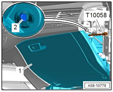
- Hex Ball Socket -T10058-
Procedure
- Remove the front passenger instrument panel side cover. Refer to → Chapter "Instrument Panel Side Cover, Removing and Installing".
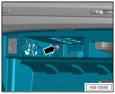
- Insert the -T10058- (or another suitable 130 mm long tool) through the opening -arrow- on the front passenger side of the instrument panel.
- Open glove compartment cover -1- by pressing down locking pin -2-.
Glove Compartment, Removing and Installing
Special tools and workshop equipment required
- Trim Removal Wedge -3409-
Removing
- Disconnect the battery ground cable with the ignition turned on. Refer to → Electrical Equipment; Rep. Gr.27; Battery; Battery, Disconnecting and Connecting.
- Remove the Information Electronics Control Module 1 -J794-. Refer to → Communication; Rep. Gr.91; Infotainment System; Component Location Overview - Infotainment System.
- Remove the bolt -arrow-.
- Remove the front passenger side instrument panel side cover. Refer to → Chapter "Instrument Panel Side Cover, Removing and Installing".
- Remove the footwell lamp. Refer to → Electrical Equipment; Rep. Gr.96; Lamps; Component Location Overview - Instrument Panel Lamps.
- Remove the glove compartment lamp. Refer to → Electrical Equipment; Rep. Gr.96; Lamps; Glove Compartment LampW6, Removing and Installing.
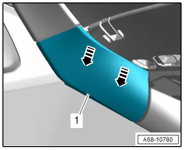
- Unclip the inner front passenger side cover -1- from the instrument panel cover using the -3409--arrows-.
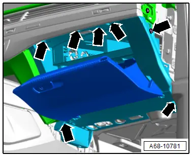
- Open the glove compartment lid and remove the screws -arrows-.
- Carefully remove the glove compartment slightly until the connectors can be disconnected.
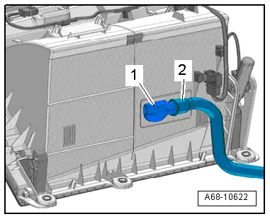
- Versions with cooling: remove the hose -2- from the vent -1- for the glove compartment cooling.
Installing
 WARNING
- Before handling pyrotechnic components (for example, connecting a connector), the person handling it must "discharge static electricity". For example, this can be done by briefly touching the door striker.
- Make sure the connectors are pushed in all the way and that they engage audibly.
Install in reverse order of removal and note the following:
- Press the connector together until it engages audibly.
 WARNING
Repairing pyrotechnic components (for example the airbag and seat belt tensioner) incorrectly increases the risk of unintentional deployments when the battery is connected.
- The ignition must be on when connecting the battery.
- For personal safety when connecting the battery, stay out of the deployment area of the airbag and maintain a distance from the seat belt tensioners/seat belts.
- Make sure that there are no other people inside the vehicle at the time when the battery is connected.
- Connect the battery ground cable with the ignition switched on. Refer to → Electrical Equipment; Rep. Gr.27; Battery; Battery, Disconnecting and Connecting.
 Note
Note
If the Airbag Indicator Lamp -K75- indicates a fault, check the DTC memory, erase it and check it again using the Vehicle Diagnostic Tester.
Installation instructions: for example tightening specifications, replacing components. Refer to → Chapter "Overview - Glove Compartment".
Glove Compartment Lid, Removing and Installing
Special tools and workshop equipment required
- T-Handle Hook -3438-
Removing
- Remove the glove compartment. Refer to → Chapter "Glove Compartment, Removing and Installing".
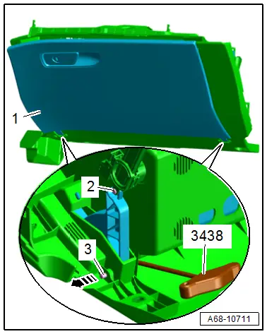
- Remove the hinge pins -2- for the glove compartment lid dampening mechanism.
- Place the glove compartment on a soft surface.
- Press out the hinge pin -3- for the glove compartment lid using the -3438- (or another suitable tool) in the direction of the -arrow- and pull it out using pliers.
- Repeat the procedure on the opposite side of the hinge pins.
- Remove the glove compartment lid -1- from the glove compartment.
Installing
Install in reverse order of removal.
Installation notes, for example tightening specifications, replacing components. Refer to → Chapter "Overview - Glove Compartment".
Glove Compartment Lid Dampening Mechanism, Removing and Installing
Removing
- Remove the glove compartment. Refer to → Chapter "Glove Compartment, Removing and Installing".
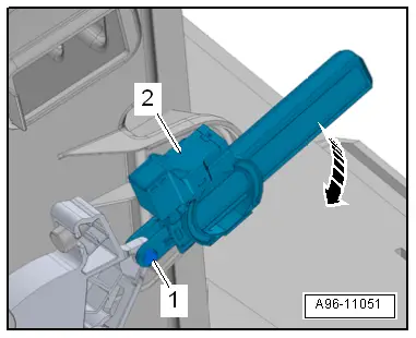
- Remove the hinge pin -1-.
- Release the dampening mechanism -2- in direction of -arrow- and remove it.
Installing
Install in reverse order of removal.
Installation notes, for example tightening specifications, replacing components. Refer to → Chapter "Overview - Glove Compartment".

