Audi Q7: Valve Block 1 in Driver Seat -N475-/ Valve Block 1 in Front Passenger Seat -N477- and Air Cushions, Removing and Installing
Removing
 WARNING
- Follow all safety precautions when working on pyrotechnic components. Refer to → Chapter "Safety Precautions for Pyrotechnic Components".
- Before handling pyrotechnic components (for example, disconnecting the connector), the person handling it must "discharge static electricity". This can be done by briefly touching the door striker pin, for example.
- Remove the backrest seat cover and cushion. Refer to → Chapter "Backrest Cover and Cushion, Removing and Installing, Seat with Pneumatic Components".
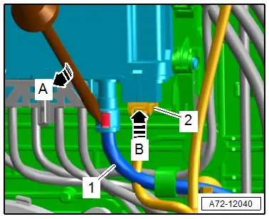
- Disconnect the connector -2- from the Valve Block 2 in Driver Seat - N476-/ Valve Block 2 in Front Passenger Seat - N478- by pressing the safety catch in direction of -arrow B-.
- Remove the pneumatic line -1- by carefully lifting the safety catch slightly with a small screwdriver in direction of -arrow A-
- Remove the Valve Block 2 in Driver Seat -N476-/ Valve Block 2 in Front Passenger Seat -N478-.
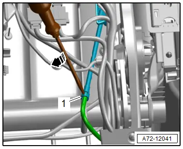
- Disconnect the pneumatic lines -1- to the seat bolster adjusters on the left and right side of the seat by carefully lifting the safety catch slightly using a small screwdriver -arrow-
- Unscrew the left and right side bolster adjuster -1- from the backrest frame -arrow- and remove.
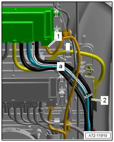
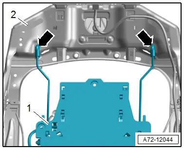
- Disconnect the connector -1- on the Valve Block 1 in Driver Seat -N475-/ Valve Block 1 in Front Passenger Seat -N477- by pressing the safety catch.
- Cut through the pneumatic line -2- to the Valve Block 1 in Driver Seat -N475-/ Valve Block 1 in Front Passenger Seat -N477-. Refer to → Chapter "Pneumatic Lines, Disconnecting and Connecting".
- Dimension -a- = 120 mm (4.7 in.)
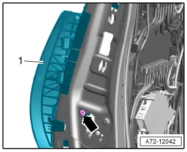
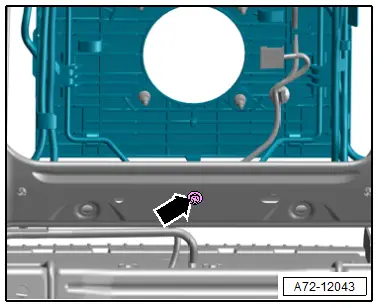
- Remove the bolt -arrow-.
- Free up the wiring harness and pneumatic lines on the module carrier.
- Move the module carrier -1- with the lumbar support air cushions forward, disengage from the backrest frame -2--arrows- and remove it.
Installing
- Cut the pneumatic lines for the new valve block according to the design of the old valve block.
- Connect the pneumatic lines. Refer to → Chapter "Pneumatic Lines, Disconnecting and Connecting".
 WARNING
- Follow all safety precautions when working on pyrotechnic components. Refer to → Chapter "Safety Precautions for Pyrotechnic Components".
- Before handling pyrotechnic components (for example, connecting the connector), the person handling it must "discharge static electricity". This can be done by briefly touching the door striker pin, for example.
- Observe all measures when installing the front seat. Refer to → Chapter "Front Seat, Removing and Installing".
Further installation is the reverse order of removal.
Installation notes, for example tightening specifications, replacing components. Refer to → Chapter "Overview - Pneumatic System, Module Carrier/Lumbar Support/Seat Bolster Adjuster".
Seat Bolster Adjuster Air Cushion, Removing and Installing
Removing
 WARNING
- Follow all safety precautions when working on pyrotechnic components. Refer to → Chapter "Safety Precautions for Pyrotechnic Components".
- Before handling pyrotechnic components (for example, disconnecting the connector), the person handling it must "discharge static electricity". This can be done by briefly touching the door striker pin, for example.
- Remove the front seat. Refer to → Chapter "Front Seat, Removing and Installing".
- Remove the seat cushion with cover. Refer to → Chapter "Seat Pan Cover and Cushion, Removing and Installing, Seat with Seat Depth Adjuster".
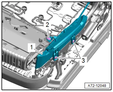
- Disconnect the pneumatic lines -1- to the seat bolster adjusters on the left and right side of the seat by carefully lifting the safety catch slightly using a small screwdriver in direction of -arrow-

- Remove the bolts -3-.
- Remove the expanding clip -2-.
- Tilt the seat bolster adjuster air cushion -1- upward and remove from the connector.
Installing
 WARNING
- Follow all safety precautions when working on pyrotechnic components. Refer to → Chapter "Safety Precautions for Pyrotechnic Components".
- Before handling pyrotechnic components (for example, connecting the connector), the person handling it must "discharge static electricity". This can be done by briefly touching the door striker pin, for example.
- Observe all measures when installing the front seat. Refer to → Chapter "Front Seat, Removing and Installing".
Install in reverse order of removal.
Installation notes, for example tightening specifications, replacing components. Refer to → Chapter "Overview - Pneumatic System, Module Carrier/Lumbar Support/Seat Bolster Adjuster".
Massage Mat, Removing and Installing
Removing
 WARNING
- Follow all safety precautions when working on pyrotechnic components. Refer to → Chapter "Safety Precautions for Pyrotechnic Components".
- Before handling pyrotechnic components (for example, disconnecting the connector), the person handling it must "discharge static electricity". This can be done by briefly touching the door striker pin, for example.
- Separate the cover and cushion. Refer to → Chapter "Backrest Cover and Cushion, Separating".
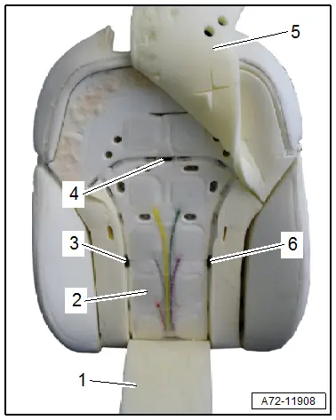
- Fold back or lift up the foam sheets -1 and 5-. Loosen them from the bonding if necessary.
- Remove the clips -3, 4 and 6-.
- Remove the massage mat -2-.
Installing
- Route the pneumatic lines in the cushion and connect them to the valve block.
- Apply the bonding at the same location it was at the time of removal.
 WARNING
- Follow all safety precautions when working on pyrotechnic components. Refer to → Chapter "Safety Precautions for Pyrotechnic Components".
- Before handling pyrotechnic components (for example, connecting the connector), the person handling it must "discharge static electricity". This can be done by briefly touching the door striker pin, for example.
Further installation is the reverse order of removal.
Installation notes, for example tightening specifications, replacing components. Refer to → Chapter "Overview - Pneumatic System, Massage Mat".
Valve Block 2 in Driver Seat -N476-/ Valve Block 2 in Front Passenger Seat -N478-, Removing and Installing
Removing
- The backrest cover must be removed. Refer to → Chapter "Backrest Cover, Removing and Installing".
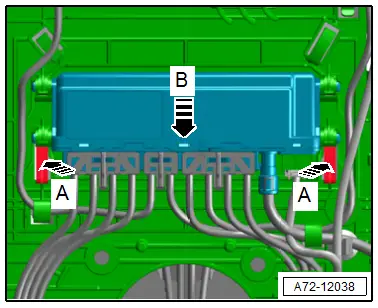
- Disengage the Valve Block 2 in Driver Seat -N476-/ Valve Block 2 in Front Passenger Seat -N478- from the module carrier in direction of -arrow B- by pressing the release buttons in direction of -arrows A-.
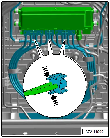
- Altogether, remove 3 pneumatic line connectors form the Valve Block 2 in Driver Seat -N476-/ Valve Block 2 in Front Passenger Seat -N478- by pressing the release buttons in direction of -arrows-.
- Disconnect the connector -2- from the Valve Block 2 in Driver Seat - N476-/ Valve Block 2 in Front Passenger Seat - N478- by pressing the safety catch in direction of -arrow B-.
- Remove the pneumatic line -1- by carefully lifting the safety catch slightly with a small screwdriver in direction of -arrow A-
- Remove the Valve Block 2 in Driver Seat -N476-/ Valve Block 2 in Front Passenger Seat -N478-.
Installing
- Route the pneumatic lines in the cushion and connect them to the valve block.
- Attach the pneumatic lines until they engage audibly.
- Attach the bonding with double adhesive tape in the same location it was in when it was removed.
 WARNING
- Follow all safety precautions when working on pyrotechnic components. Refer to → Chapter "Safety Precautions for Pyrotechnic Components".
- Before handling pyrotechnic components (for example, connecting the connector), the person handling it must "discharge static electricity". This can be done by briefly touching the door striker pin, for example.
Further installation is the reverse order of removal.
Installation notes, for example tightening specifications, replacing components. Refer to → Chapter "Overview - Pneumatic System, Massage Mat".

Pneumatic Seat Compressor, Removing and Installing
Removing
- Switch off the ignition.
- Unscrew the front seat and tip to the rear with the wires attached. Refer to → Chapter "Front Seat, Removing and Installing".
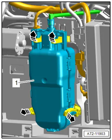
- Remove the rubber fastener from the brackets on the compressor -1- in direction of -arrows-.
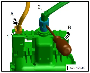
- Press the safety catch in direction of -arrow A- to disconnect the connector -1-
- Remove the pneumatic line -2- by carefully lifting the safety catch slightly with a small screwdriver in direction of -arrow B-
Installing
- Attach the pneumatic line until it audibly locks into place.
Install in reverse order of removal.
Installation notes, for example tightening specifications, replacing components. Refer to → Chapter "Overview - Pneumatic System, Compressor".

