Audi Q7: Instrument cluster overview
Audi Q7 (4M) 2016-2026 Owner's Manual / Display and operation / Instrument cluster / Instrument cluster overview
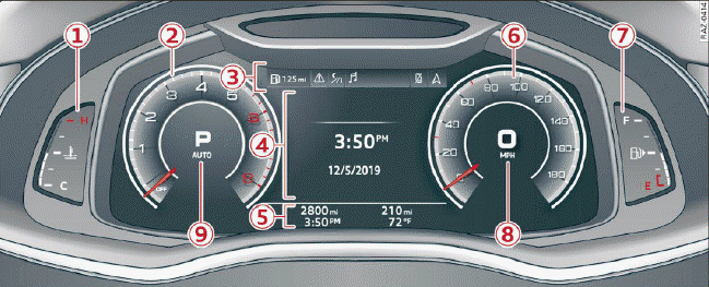
Fig. 2 Instrument cluster overview (Audi virtual cockpit)
Depending on the vehicle equipment, the following items may appear in the instrument cluster:
- Display
- Engine coolant temperature
.png)
- Engine coolant temperature
- Left dial
- Tachometer
- Tab area
- Central area
- Status line (one or two lines)
- Right dial
- Convenience display
- Fuel level

- Right additional display with speedometer
- Left additional display with:
- Selector lever position
- Audi drive select mode
WARNING
If there is a serious system malfunction, the display may turn off. The
 indicator light may also turn on.
Stop the vehicle safely. See an authorized Audi dealer or authorized Audi
Service Facility for assistance.
indicator light may also turn on.
Stop the vehicle safely. See an authorized Audi dealer or authorized Audi
Service Facility for assistance.
Tips
- You can select the units used for temperature, speed, and other measurements in the Infotainment system.
- Speeds are displayed in mph (miles per hour) or km/h (kilometers per hour).
- Certain instrument cluster content can also be displayed in the head-up display.

