Audi Q7: Overview - Interior Rearview Mirror
Audi Q7 (4M) 2016-2026 Workshop Manual / Body / Body Interior / Interior Equipment / Overview - Interior Rearview Mirror
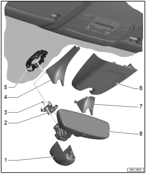
1 - Front Cover
- For the mirror base
- Press on until it engages audibly
2 - Clip
- For the interior rearview mirror
- There are different versions. Refer to the Parts Catalog for the allocation.
- Replace after removing the interior rearview mirror
3 - Bolt
- 1.5 Nm
- Quantity: 2
4 - Rear Cover
- For the mirror base
- For the interior rearview mirror without optional equipment
- Press on until it engages audibly
5 - Baseplate
- For the interior rearview mirror
- Bonded to the windshield
6 - Cover
- For the control module sensor
- For the interior rearview mirror with optional equipment
- Press on until it engages audibly
7 - Rear Cover
- For the mirror base
- For the interior rearview mirror with optional equipment
- Press on until it engages audibly
8 - Interior Rearview Mirror
- Equipment level: with integrated Automatic High Beam Assist Control Module -J844-
- The Automatic High Beam Assist Control Module -J844- cannot be replaced separately. Replace the interior rearview mirror if faulty
- Removing and installing. Refer to → Chapter "Interior Rearview Mirror, Removing and Installing".
- Attach in the installed location while turned to 20º and turn it clockwise all the way
- Replace the clip after removing

