Audi Q7: Overview - Pedestrian Protection
Audi Q7 (4M) 2016-2026 Workshop Manual / Body / Body Interior / Passenger Protection, Airbags, Seat Belts / Overview - Pedestrian Protection
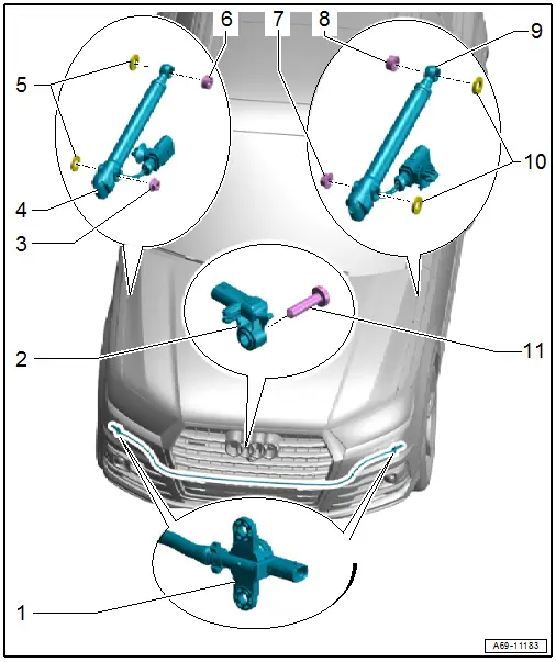
1 - Driver Side Pedestrian Protection Crash Sensor 2 -G851-/Front Passenger Side Pedestrian Protection Crash Sensor 2 -G852-
- Unit with pressure hose
- Component location: in the molded foam part on the impact member
- Must be replaced when
- The molded foam part is visibly damaged.
- The impact member is visibly deformed.
- The bumper cover is deformed.
- The pressure hose is damaged.
- Place the pressure hose in the groove on the molded foam part.
- Insert the pressure hose in the center of the molded foam part, the projecting end is the same on both the left and right side.
- Do not kink or squeeze the pressure hose.
- Removing and Installing. Refer to → Chapter "Pedestrian Protection Crash Sensor, Removing and Installing".
2 - Pedestrian Protection Center Crash Sensor -G693-
- Installation location: on the bumper cover
- Removing and installing. Refer to → Chapter "Pedestrian Protection Center Crash Sensor -G693-, Removing and Installing".
3 - Nut
- 8 Nm
4 - Pedestrian Protection Trigger 1 -G598-
- Removing and installing. Refer to → Chapter "Pedestrian Protection Trigger 1 -G598-/ Pedestrian Protection Trigger 2 -G599-, Removing and Installing".
5 - Seals
6 - Clip
7 - Nut
- 8 Nm
8 - Clip
9 - Pedestrian Protection Trigger 2 -G599-
- Removing and installing. Refer to → Chapter "Pedestrian Protection Trigger 1 -G598-/ Pedestrian Protection Trigger 2 -G599-, Removing and Installing".
10 - Seals
11 - Bolt
- 6 Nm

