Audi Q7: Overview - Window Regulator
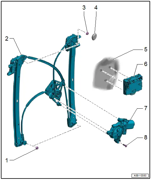
1 - Nut
- 7 Nm
2 - Window Regulator
- Removing and Installing. Refer to → Chapter "Window Regulator, Removing and Installing".
3 - Nut
- 7 Nm
4 - Cap
5 - Door
6 - Rear Door Control Module
- Driver Side Rear Door Control Module -J926-
- Passenger Side Rear Door Control Module -J927-
- Component Location Overview. Refer to → Chapter "Component Location Overview - Central Locking".
7 - Rear Power Window Motor
- Driver Side Rear Window Regulator Motor -V471-
- Passenger Side Rear Window Regulator Motor -V472-
- Removing and Installing. Refer to → Chapter "Window Regulator Motor, Removing and Installing".
8 - Bolt
- 3.5 Nm
- Quantity: 3
- Thread cutting
- Position and install by hand
Overview - Door Handle and Door Lock
Overview - Door Handle and Mounting Bracket
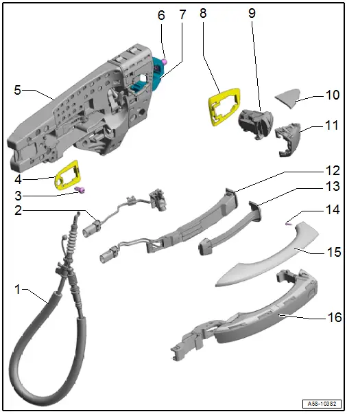
1 - Door Opener Operating Cable
- Removing and Installing. Refer to → Chapter "Door Opener Operating Cable, Removing and Installing".
2 - Exterior Door Handle Illumination Bulb
- Left Rear Exterior Door Handle Illumination Bulb -L168-
- Right Rear Exterior Door Handle Illumination Bulb -L169-
- Overview. Refer to → Electrical Equipment; Rep. Gr.94; Exterior Door Handle Lamps; Overview - Exterior Door Handle Lamps.
3 - Bolt
- 2.5 Nm
4 - Front Backing Plate
- Removing and Installing. Refer to → Chapter "Mounting Bracket, Removing and Installing".
5 - Mounting Bracket
- Removing and Installing. Refer to → Chapter "Mounting Bracket, Removing and Installing".
6 - Clamping Screw
- 2.5 Nm
- For the housing
7 - Retaining Bracket
8 - Rear Backing Plate
- Removing and Installing. Refer to → Chapter "Mounting Bracket, Removing and Installing".
9 - Housing
- Removing and Installing. Refer to → Chapter "Housing, Removing and Installing".
10 - Trim Molding
- For the cap
- Equipped on some models
- Removing and Installing. Refer to → Chapter "Trim Molding Cap, Removing and Installing".
11 - Cap
- For the housing
- There are different versions. Refer to the → Electronic Parts Catalog (ETKA) for the allocation.
- Removing and Installing. Refer to → Chapter "Housing Cap, Removing and Installing".
12 - Exterior Door Handle Touch Sensor
- Left Rear Exterior Door Handle Touch Sensor -G417-
- Right Rear Exterior Door Handle Touch Sensor -G418-
- Equipped on some models
- Overview. Refer to → Electrical Equipment; Rep. Gr.94; Access/Start Authorization; Component Location Overview - Keyless Access Authorization System.
13 - Door Handle Trim
- Removing and Installing. Refer to → Chapter "Door Handle Trim, Removing and Installing".
- Push in until it clicks into place
14 - Bolt
- 1 Nm
- For versions with trim molding
15 - Trim Molding
- For the door handle
- Equipped on some models
- Removing and Installing. Refer to → Chapter "Door Handle Trim Molding, Removing and Installing".
16 - Door Handle
- There are different versions. Refer to the Parts Catalog for the allocation.
- Removing and Installing. Refer to → Chapter "Door Handle, Removing and Installing".
Overview - Door Lock and Striker, Versions without Closing Assist
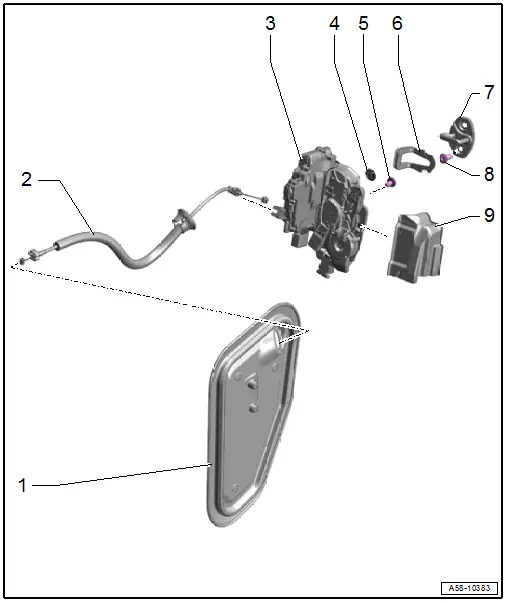
1 - Door Inner Cover
- Removing and Installing. Refer to → Chapter "Door Inner Cover, Removing and Installing".
2 - Door Opener Operating Cable
- With grommet
- Removing and Installing. Refer to → Chapter "Door Opener Operating Cable, Removing and Installing".
3 - Door Lock
- Removing and Installing. Refer to → Chapter "Door Lock, Removing and Installing".
4 - Plugs
5 - Bolt
- 19 Nm
- Quantity: 2
6 - Seal
- Replace if damaged
7 - Striker
- Removing and Installing. Refer to → Chapter "Striker, Removing and Installing".
8 - Bolt
- 25 Nm
- Quantity: 2
9 - Cover
- For the door lock
- Installation position. Refer to → Fig.
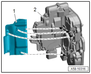
Installation Position for Door Lock Cover
- Push the cover -1- on the door lock -2- until it engages -arrows-.
Overview - Door Lock and Striker, Versions with Closing Assist
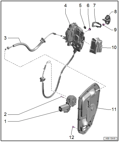
1 - Rear Closing Assist Motor
- Left Rear Closing Assist Motor -V307-
- Right Rear Closing Assist Motor -V308-
- Removing and Installing. Refer to → Chapter "Closing Assist Motor, Removing and Installing".
2 - Bolt
- 1.5 Nm
- Quantity: 3
3 - Door Opener Operating Cable
- Removing and Installing. Refer to → Chapter "Door Opener Operating Cable, Removing and Installing".
4 - Door Lock
- Removing and Installing. Refer to → Chapter "Door Lock, Removing and Installing".
5 - Plugs
6 - Bolt
- 19 Nm
- Quantity: 2
7 - Seal
- Replace if damaged
8 - Striker
- Removing and Installing. Refer to → Chapter "Striker, Removing and Installing".
9 - Bolt
- 25 Nm
- Quantity: 2
10 - Cover
- For the door lock
- Installation position. Refer to → Fig.
11 - Door Inner Cover
- Removing and Installing. Refer to → Chapter "Door Inner Cover, Removing and Installing".
12 - Expanding Pin
- Quantity: 11
Overview - Window Guides and Window Shaft Strips
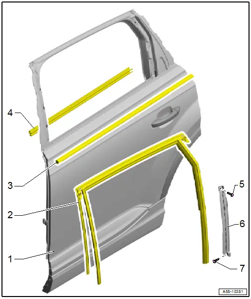
1 - Door
2 - Window Guide
- Removing and Installing. Refer to → Chapter "Window Guide, Removing and Installing".
3 - Outer Window Shaft Strip
- Removing and Installing. Refer to → Chapter "Outer Window Shaft Strip, Removing and Installing".
4 - Inner Window Shaft Strip
- Removing and Installing. Refer to → Chapter "Inner Window Shaft Strip, Removing and Installing".
5 - Bolt
- 2.5 Nm
6 - Guide Rail
- For the door window
- Removing and Installing. Refer to → Chapter "Door Window Guide Rail, Removing and Installing".
7 - Bolt
- 3.5 Nm

