Audi Q7: Parallel Parking Assist
Overview - Parallel Parking Assist
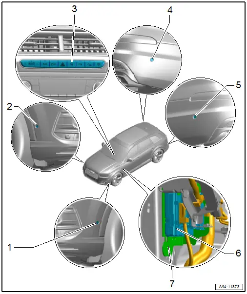
1 - Left Front Parallel Parking Assistance Sensor -G568-
- Removing and installing. Refer to → Chapter "Front Sensor, Removing and Installing".
2 - Right Front Parallel Parking Assistance Sensor -G569-
- Removing and installing. Refer to → Chapter "Front Sensor, Removing and Installing".
3 - Parallel Parking Assistance Button -E581-
- A component of the Control Unit 1 for Driving and Convenience Functions -E791-
- Removing and installing. Refer to → Chapter "Buttons in Instrument Panel, Removing and Installing, Control Unit 1 for Driving and Convenience Functions -E791-".
4 - Right Rear Parallel Parking Assistance Sensor -G717-
- Removing and installing. Refer to → Chapter "Rear Sensor, Removing and Installing".
5 - Left Rear Parallel Parking Assistance Sensor -G716-
- Removing and installing. Refer to → Chapter "Rear Sensor, Removing and Installing".
6 - Vehicle Electrical System Control Module -J519-
- Component location overview. Refer to → Chapter "Component Location Overview - Control Modules".
7 - Bracket
- For vehicle electrical system control module
Front Sensor, Removing and Installing
Removing
- Remove the front wheel housing liner front section. Refer to → Body Exterior; Rep. Gr.66; Wheel Housing Liner; Front Wheel Housing Liner, Removing and Installing.
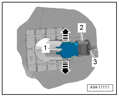
- Press both tabs -arrows- to the side and press the sensor -1- inward from the outside.
- Disconnect the connector -2- by sliding the retainer -3- toward the rear and pressing the release down.

Installing
Install in reverse order of removal.
Rear Sensor, Removing and Installing
Removing
- Reach behind the bumper cover and expand both tabs in direction of -arrows- while pushing the sensor -1- from the outside toward the inside at the same time.
- Disconnect the connector -2- by sliding the retainer -3- toward the rear and pressing the release down.
Installing
Install in reverse order of removal.
Automatic Headlamp Range Control
Overview - Automatic Headlamp Range Control
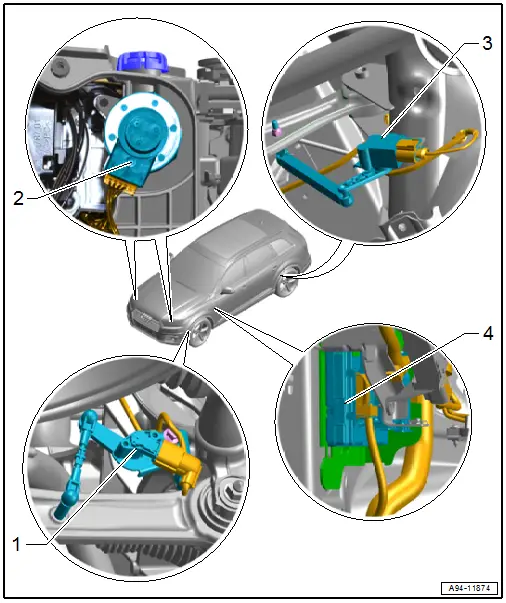
1 - Left Front Level Control System Sensor -G78-
- Component location: On the front control arm
- Only for vehicles with LED Matrix headlamps
- Removing and installing. Refer to → Suspension, Wheels, Steering; Rep. Gr.43; Level Control System Sensor; Left/Right Front Level Control System Sensor G78/G289, Removing and Installing.
2 - Headlamp Beam Adjustment Motor
- Left Headlamp Beam Adjustment Motor -V48-, Right Headlamp Beam Adjustment Motor -V49-
- Removing and installing. Refer to → Chapter "Left and Right Headlamp Beam Adjustment Motor -V48-/-V49-, Removing and Installing".
3 - Left Rear Level Control System Sensor -G76-
- Component location: On the rear control arm
- Removing and installing. Refer to → Suspension, Wheels, Steering; Rep. Gr.43; Level Control System Sensor; Left/Right Rear Level Control System Sensor G76/G77, Removing and Installing.
4 - Vehicle Electrical System Control Module -J519-
- Component location overview. Refer to → Chapter "Component Location Overview - Control Modules".
Special Tools
Special tools and workshop equipment required
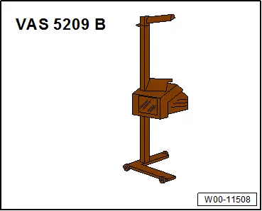
- Headlamp Adjusting Unit -VAS5209B- or
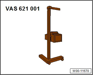
- Headlight Adjusting Unit -VAS621001-
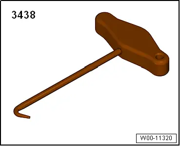
- T-Handle Hook -3438-