Audi Q7: Steering Column Switch Module
Overview - Steering Column Switch Module
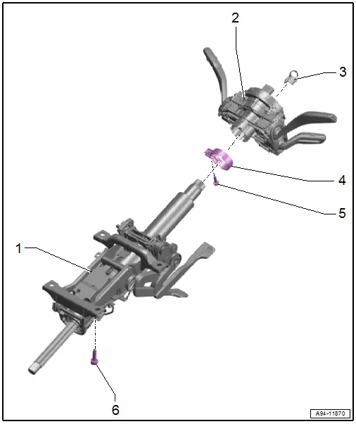
1 - Steering Column
2 - Steering Column Switch Module
- With the following integrated components:
- Turn Signal Switch -E2-
- Windshield Wiper Intermittent Mode Switch -E22-
- Cruise Control Switch -E45-
- Steering Column Electronics Control Module -J527-
- Airbag Spiral Spring/Return Spring with Slip Ring -F138-
- Steering Angle Sensor -G85-
- The components cannot be replaced separately.
- If faulty replace a component of the switch module
- Removing and installing. Refer to → Chapter "Steering Column Switch Module, Removing and Installing".
3 - Transportation Protection
- Remove before installing the steering wheel
4 - Locking Ring
5 - Bolt
- 4 Nm
6 - Bolt
- Tightening specification. Refer to → Suspension, Wheels, Steering; Rep. Gr.48; Steering Column; Overview - Steering Column.
Steering Column Switch Module, Removing and Installing
- If replacing the control module, select the "Replace control module" function for the corresponding control module on the Vehicle Diagnostic Tester.
Removing
- Remove the steering wheel. Refer to → Suspension, Wheels, Steering; Rep. Gr.48; Steering Wheel; Steering Wheel, Removing and Installing.
- Remove the steering column trim panels. Refer to → Body Interior; Rep. Gr.68; Storage Compartments and Covers; Overview - Steering Column Trim Panel.
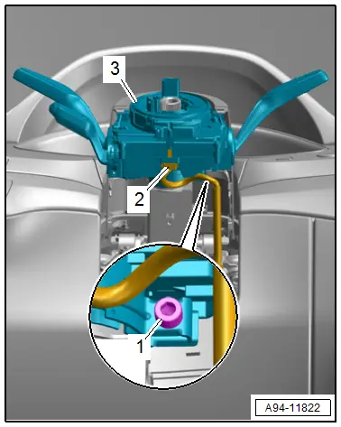
- Remove the bolt -1-.
- Disconnect the connector -2-.
- Remove the steering column switch module -3-.
Installing
Install in reverse order of removal.
Tightening Specifications
- Refer to → Chapter "Overview - Steering Column Switch Module"

