Audi Q7: Technical Data
Transmission/Engine Allocation
Codes, Transmission Allocation, Ratios, Audi A4
- Production time period.
- Allocation to engine
- Allocation to the automatic transmission via the codes and PR numbers
Codes, Transmission Allocation, Ratios, Audi Q7
Refer to the Parts Catalog for the Following Information.
- Production time period.
- Allocation to engine
- Allocation to the automatic transmission via the codes and PR numbers
Capacities
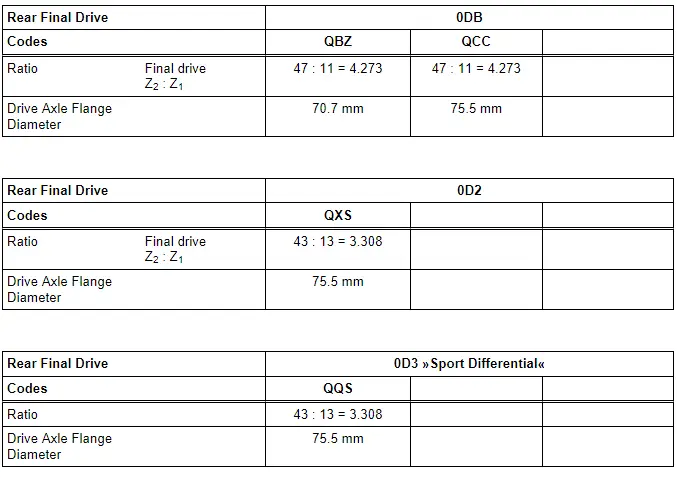
Capacities, Rear Final Drive 0DB
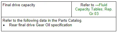
- Checking gear oil level. Refer to → Chapter "Gear Oil, Checking Level".
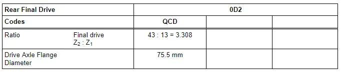
Capacities, Rear Final Drive 0D2
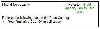
- Checking gear oil level. Refer to → Chapter "Gear Oil, Checking Level".
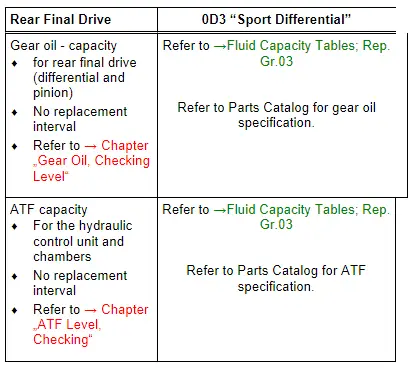
Capacities, Rear Final Drive 0D3 "Sport Differential"
Overview - Transmission
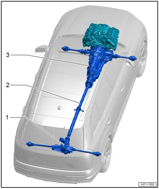
1 - Rear Final Drive
- Overview. Refer to → Chapter "Overview - Final Drive".
- Removing and installing. Refer to → Chapter "Final Drive".
2 - Driveshaft
- Overview. Refer to → Chapter "Overview - Driveshaft".
- Removing and installing. Refer to → Chapter "Driveshaft, Removing and Installing".
3 - Transmission
- Removing and installing. Refer to → 8-Speed Automatic Transmission; Rep. Gr.37; Transmission, Removing and Installing.

