Audi Q7: Technical Data
Capacities
Capacities, ATF Area in the Transmission
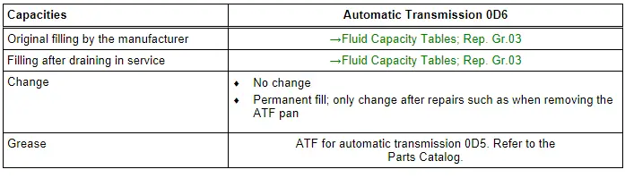
 Caution
There is a risk that the transmission could malfunction or fail.
Only use the ATF available as a replacement part with the 0D5 automatic transmission. Refer to the Parts Catalog.
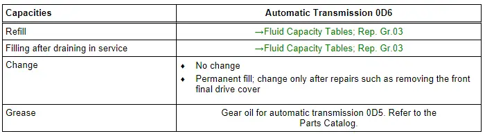
Front Final Drive Capacities
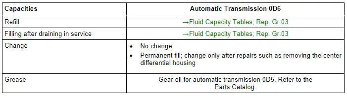
Transfer Case Capacities
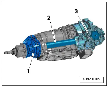
Oil Distribution
Transmission with Separated Oil System
- The protective pipe -2- is free of oil, the transfer case -1- and the front final drive -3- is sealed with a gasket to side shaft.
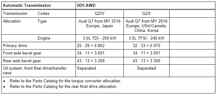
- Allocation. Refer to → Chapter "Transmission/Engine Allocation".
Transmission with Combined Oil System
- The oil chambers inside the front final drive -3- and inside the transfer case -1- are consolidated via the protective pipe -2-.
- The side shaft runs in gear oil in the protective pipe.
- Allocation. Refer to → Chapter "Transmission/Engine Allocation".
Transmission/Engine Allocation
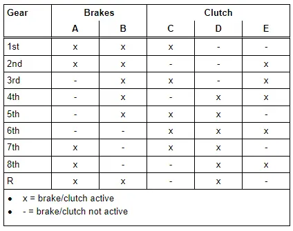
Clutch Logic
Overview - Transmission
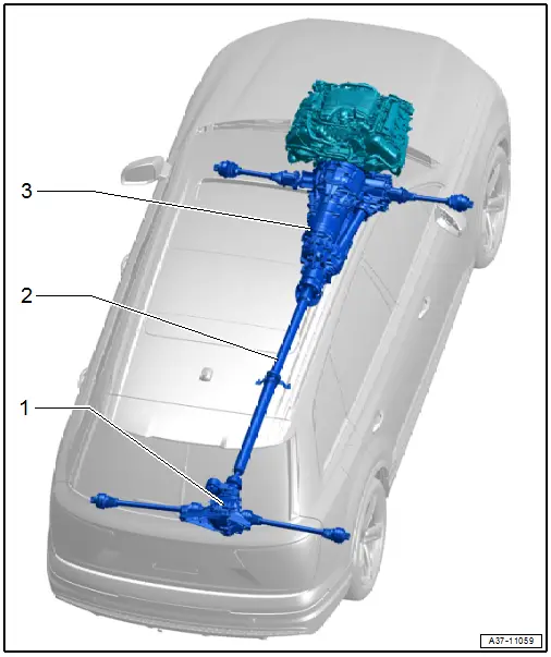
1 - Rear Final Drive
- Removing and installing. Refer to → Rear Final Drive 0D2, 0D3, 0DB; Rep. Gr.39; Final Drive; Final Drive, Removing and Installing.
2 - Driveshaft
- Removing and installing. Refer to → Rear Final Drive 0D2, 0D3, 0DB; Rep. Gr.39; Driveshaft; Driveshaft, Removing and Installing.
3 - Automatic Transmission 0D6

