Audi Q7: Overview - Final Drive
Audi Q7 (4M) 2016-2026 Workshop Manual / Drivetrain / Rear Final Drive, Differential / Final Drive / Overview - Final Drive
Overview - Rear Final Drive
Rear Final Drive
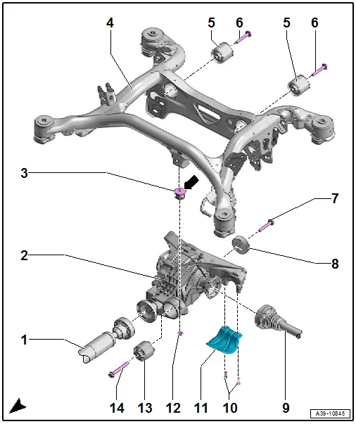
1 - Driveshaft
- Removing and installing. Refer to → Chapter "Driveshaft, Removing and Installing".
- Removing and installing on the rear final drive. Refer to → Chapter "Drive Shaft, Removing from Rear Final Drive and Installing".
2 - Rear Final Drive
- Refer to → Chapter "Final Drive, Removing and Installing"
3 - Auxiliary Mount
- 20 Nm
- Tightening is only permitted via the upper hex fitting -arrow-.
- Not installed on all versions
4 - Subframe
- Removing and installing. Refer to → Suspension, Wheels, Steering; Rep. Gr.42; Subframe; Overview - Subframe.
5 - Rear Bonded Rubber Bushing
- Removing and installing. Refer to → Suspension, Wheels, Steering; Rep. Gr.42; Subframe; Overview - Subframe.
6 - Bolt
- 90 Nm + 90º
- Always replace.
7 - Bolt
- 55 Nm + 90º
- Always replace.
8 - Vibration Damper
- Not installed on all versions
Installation position:
- The inner protruding collar points toward the final drive
9 - Drive Axle
- Removing and installing. Refer to → Suspension, Wheels, Steering; Rep. Gr.42; Drive Axle; Drive Axle, Removing and Installing.
10 - Bolt
- 23 Nm
11 - Heat Shield
12 - Nut
- 20 Nm
- Not installed on all versions
13 - Front Bonded Rubber Bushing
14 - Bolt
- 130 Nm + 180º
- Always replace.

