Audi Q7: Tower Brace, Removing and Installing
Tower Brace Additional Reinforcement, Removing and Installing, Q7 without High-Voltage System
Special tools and workshop equipment required
- Pry Lever -80-200-
- Torque Wrench 1331 5-50Nm -VAG1331-
Removing
- Remove the plenum chamber cover. Refer to → Body Exterior; Rep. Gr.50; Bulkhead; Plenum Chamber Cover, Removing and Installing.
- Remove the Engine Control Module -J623- from the bracket and set aside. Refer to → 6-Cyl. TDI Common Rail 3,0l 4V Motor (EA 897 Gen I); Rep. Gr.23; Engine Control Module; Engine Control ModuleJ623, Removing and Installing or → 6-Cylinder Direct Injection 3.0L 4V TFSI Supercharged Engine; Rep. Gr.24; Engine Control Module; Engine Control ModuleJ623, Removing and Installing.
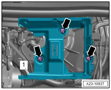
- Remove the nuts -arrows- and push the bracket -1- for the engine control module slightly forward.
- Unclip the left and right cover from the bulkhead. Refer to → Body Exterior; Rep. Gr.50; Bulkhead; Overview - Bulkhead.
- Remove the right E-Box from the bulkhead and push it slightly forward. Refer to → Electrical Equipment; Rep. Gr.97; Relay Panels, Fuse Panels and E-Boxes.
- Remove the air filter housing. Refer to → Rep. Gr.23; Air Filter; Air Filter Housing, Removing and Installing or → Rep. Gr.24; Air Filter; Air Filter Housing, Removing and Installing.
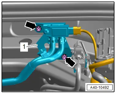
- If equipped, remove the nuts -arrows- and move the bracket -1- for the Differential Pressure Sensor -G505- to the side.
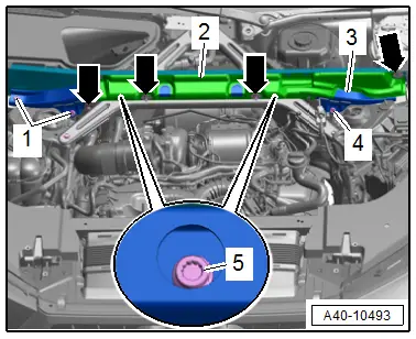
- Loosen the clamps -arrows- with the Pry Lever -80-200- and pivot the trim panel -2- upward.
- Remove the bolts -1, 4 and 5- and remove the additional reinforcement -3- with the plenum chamber bulkhead.
Installing
Install in reverse order of removal and note the following:
- Install the air filter housing. Refer to → Rep. Gr.23; Air Filter; Air Filter Housing, Removing and Installing or → Rep. Gr.24; Air Filter; Air Filter Housing, Removing and Installing.
- Install the plenum chamber cover. Refer to → Body Exterior; Rep. Gr.50; Bulkhead; Plenum Chamber Cover, Removing and Installing.
Tightening Specifications
- Refer to → Chapter "Overview - Suspension Strut and Upper Control Arm"
- Refer to → Electrical Equipment; Rep. Gr.97; Relay Panels, Fuse Panels and E-Boxes
- Refer to → Rep. Gr.23; Heated Oxygen Sensor; Overview - Heated Oxygen Sensor.
Tower Brace, Removing and Installing, Q7 without High-Voltage System
Special tools and workshop equipment required
- Torque Wrench 1331 5-50Nm -VAG1331-
Removing
- Remove the additional reinforcement for the tower brace. Refer to → Chapter "Tower Brace Additional Reinforcement, Removing and Installing, Q7 without High-Voltage System".
- Free up the wires.
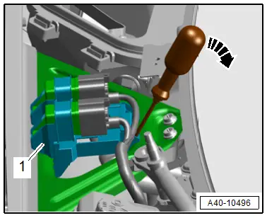
- Release the catches with a screwdriver in direction of -arrow- and remove the bracket -1- for the relay and control module and set aside.
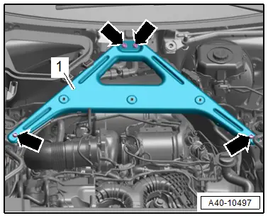
- Remove the bolts -arrows- and remove the tower brace -1-.
Installing
Install in reverse order of removal and note the following:
- Install the additional support for the tower brace. Refer to → Chapter "Tower Brace Additional Reinforcement, Removing and Installing, Q7 without High-Voltage System".
Tightening Specifications
- Refer to → Chapter "Overview - Suspension Strut and Upper Control Arm"
Tower Brace with Additional Reinforcement, Removing and Installing, Q7 e-tron
Special tools and workshop equipment required
- Pry Lever -80-200-
- Torque Wrench 1331 5-50Nm -V.A.G 1331-
Removing
- Remove the plenum chamber cover. Refer to → Body Exterior; Rep. Gr.50; Bulkhead; Plenum Chamber Cover, Removing and Installing.
- Remove the Engine Control Module -J623- from the bracket and set aside. Refer to → 6-Cyl. TDI Common Rail 3,0l 4V Motor (EA 897 Gen I); Rep. Gr.23; Engine Control Module; Engine Control ModuleJ623, Removing and Installing or → 6-Cylinder Direct Injection 3.0L 4V TFSI Supercharged Engine; Rep. Gr.24; Engine Control Module; Engine Control ModuleJ623, Removing and Installing.
- Remove the nuts -arrows- and push the bracket -1- for the engine control module slightly forward.
- Unclip the left and right cover from the bulkhead. Refer to → Body Exterior; Rep. Gr.50; Bulkhead; Overview - Bulkhead.
- Remove the right E-Box from the bulkhead and push it slightly forward. Refer to → Electrical Equipment; Rep. Gr.97; Relay Panels, Fuse Panels and E-Boxes.
- Remove the air filter housing. Refer to → Rep. Gr.23; Air Filter; Air Filter Housing, Removing and Installing or → Rep. Gr.24; Air Filter; Air Filter Housing, Removing and Installing.

- Remove the nuts -arrows- and move the bracket -1- for the Differential Pressure Sensor -G505- to the side.

- Release the catches with a screwdriver in direction of -arrow- and remove the bracket -1- for the relay and control module and set aside.

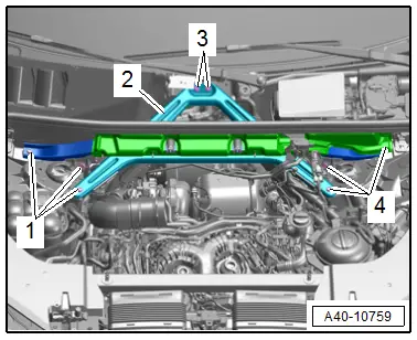
- Remove the bolts -1, 3 and 4- and remove the tower brace -2- with additional reinforcement and plenum chamber end plate.
Installing
Install in reverse order of removal and note the following:
- Install the air filter housing. Refer to → Rep. Gr.23; Air Filter; Air Filter Housing, Removing and Installing or → Rep. Gr.24; Air Filter; Air Filter Housing, Removing and Installing.
- Install the plenum chamber cover. Refer to → Body Exterior; Rep. Gr.50; Bulkhead; Plenum Chamber Cover, Removing and Installing.
Tightening Specifications
- Refer to → Chapter "Overview - Suspension Strut and Upper Control Arm"
- Refer to → Electrical Equipment; Rep. Gr.97; Relay Panels, Fuse Panels and E-Boxes
- Refer to → Rep. Gr.23; Heated Oxygen Sensor; Overview - Heated Oxygen Sensor.

