Audi Q7: Upper Transverse Link, Removing and Installing
Upper Transverse Link, Removing and Installing
Special tools and workshop equipment required
- Torque Wrench 1332 40-200Nm -VAG1332-
- Engine and Gearbox Jack -VAS6931-
- Engine/Gearbox Jack Adapter - Wheel Hub Support -T10149-
Removing
Before starting work:
- Versions with coil springs: determine the curb weight position. Refer to → Chapter "Wheel Bearing in Curb Weight Position, Lifting Vehicles with Coil Spring".
- Versions with air suspension: determine the standard vehicle height. Refer to → Chapter "Wheel Bearing at Standard Vehicle Height, Lifting Vehicles with Air Suspension".
- Remove the rear wheel. Refer to → Chapter "Wheels and Tires".
- Turn the wheel hub, until the wheel bolt hole is on top.
![]() Caution
Caution
Risk of destroying the wheel bearing when installing the wheel bolt.
So that the installed wheel bolt cannot push against the wheel bearing, it (the bolt) must be installed with a washer inserted in between.
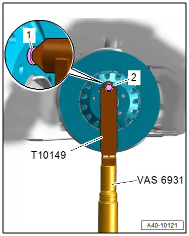
- Install the Engine/Gearbox Jack Adapter - Wheel Hub Support -T10149- with a wheel bolt -2- and inserted washer -1- on the wheel hub.
- Slightly lift the wheel bearing housing using the Engine/Gearbox Jack Adapter - Wheel Hub Support -T10149- with the Engine and Gearbox Jack -VAS6931- this allows the threaded connections to easily separate.
![]() WARNING
WARNING
Risk of accident!
- Do not lift or lower the vehicle when the Engine and Gearbox Jack -VAS6931- is under the vehicle.
- Do not leave the Engine and Gearbox Jack -VAS6931- under the vehicle any longer than necessary.

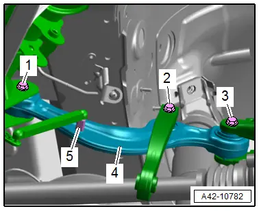
- Disconnect the threaded connections -1, 3 and 5-.
- Remove the bolt -1- and remove the upper transverse link -4-.
Installing
Install in reverse order of removal and note the following:
- Install the threaded connections only until stop but do not yet tighten.
![]() Note
Note
Bonded rubber bushings have a limited range of motion. Only tighten suspension bolts when vehicle is in curb weight position or at standard vehicle height.
- Lifting the wheel bearing in curb weight position (refer to → Chapter "Wheel Bearing in Curb Weight Position, Lifting Vehicles with Coil Spring") or at standard vehicle height (refer to → Chapter "Wheel Bearing at Standard Vehicle Height, Lifting Vehicles with Air Suspension").
- Overview table for if an axle alignment is necessary. Refer to → Chapter "Need for Axle Alignment, Evaluating".
Tightening Specifications
- Refer to → Chapter "Overview - Transverse Link"
- Refer to → Chapter "Overview - Stabilizer Bar"
- Refer to → Chapter "Overview - Rear Level Control System Sensor"
Rear Upper Transverse Link, Removing and Installing
Special tools and workshop equipment required
- Torque Wrench 1332 40-200Nm -VAG1332-
- Engine and Gearbox Jack -VAS6931-
- Engine/Gearbox Jack Adapter - Wheel Hub Support -T10149-
- 14 mm internal multi-point socket with corner extension, commercially available
![]() Note
Note
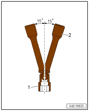
To keep from having to lower the subframe use a 14 mm internal multi-point bolt -1- with a corner extension -2-.
Removing
Before starting work:
- Versions with coil springs: determine the curb weight position. Refer to → Chapter "Wheel Bearing in Curb Weight Position, Lifting Vehicles with Coil Spring".
- Versions with air suspension: determine the standard vehicle height. Refer to → Chapter "Wheel Bearing at Standard Vehicle Height, Lifting Vehicles with Air Suspension".
- Remove the rear wheel. Refer to → Chapter "Wheels and Tires".
- Remove the wheel housing liner. Refer to → Body Exterior; Rep. Gr.66; Wheel Housing Liner; Rear Wheel Housing Liner, Removing and Installing.
Right Transverse Link:
- Versions with 3.0L TDI engine: remove the SCR tank. Refer to → 6-Cyl. TDI Common Rail 3,0l 4V Motor (EA 897 Gen I); Rep. Gr.26; Selective Catalytic Reduction System; Reducing Agent Tank, Removing and Installing.
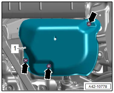
- Versions with air suspension: remove the nuts -arrows- and the cover -1- for the air supply unit.
Continuation for Both Sides:
- Turn the wheel hub, until the wheel bolt hole is on top.
![]() Caution
Caution
Risk of destroying the wheel bearing when installing the wheel bolt.
So that the installed wheel bolt cannot push against the wheel bearing, it (the bolt) must be installed with a washer inserted in between.
- Install the Engine/Gearbox Jack Adapter - Wheel Hub Support -T10149- with a wheel bolt -2- and inserted washer -1- on the wheel hub.
- Slightly lift the wheel bearing housing using the Engine/Gearbox Jack Adapter - Wheel Hub Support -T10149- with the Engine and Gearbox Jack -VAS6931- this allows the threaded connections to easily separate.
![]() WARNING
WARNING
Risk of accident!
- Do not lift or lower the vehicle when the Engine and Gearbox Jack -VAS6931- is under the vehicle.
- Do not leave the Engine and Gearbox Jack -VAS6931- under the vehicle any longer than necessary.
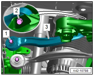
- Remove the bolts -1 and 2- and remove the upper transverse link -3-.
Installing
Install in reverse order of removal and note the following:
- Install the threaded connections only until stop but do not yet tighten.
![]() Note
Note
Bonded rubber bushings have a limited range of motion. Only tighten suspension bolts when vehicle is in curb weight position or at standard vehicle height.
- Lifting the wheel bearing in curb weight position (refer to → Chapter "Wheel Bearing in Curb Weight Position, Lifting Vehicles with Coil Spring") or at standard vehicle height (refer to → Chapter "Wheel Bearing at Standard Vehicle Height, Lifting Vehicles with Air Suspension").
- Overview table for if an axle alignment is necessary. Refer to → Chapter "Need for Axle Alignment, Evaluating".
Tightening Specifications
- Refer to → Chapter "Overview - Transverse Link"

