Audi Q7: Backrest Cover and Cushion, Removing and Installing
Backrest Cover and Cushion, Removing and Installing, Seat without Pneumatic Components
Special tools and workshop equipment required
- Pry Lever -80-200-
- Trim Removal Wedge -3409-
Removing
 WARNING
Before handling pyrotechnic components (for example, disconnecting the connector), the person handling it must "discharge static electricity". This can be done by briefly touching the door striker pin, for example.
- Remove the front seat. Refer to → Chapter "Front Seat, Removing and Installing".
- Fasten the front seat on the -VAS6136-. Refer to → Chapter "Front Seat, Mounting on Fixture for Seat Repair".
- Remove the headrest. Refer to → Chapter "Headrest, Removing and Installing".
- Remove the backrest cover. Refer to → Chapter "Backrest Cover, Removing and Installing".
- Disconnect the backrest heating wiring harness on the seat pan and free it up.
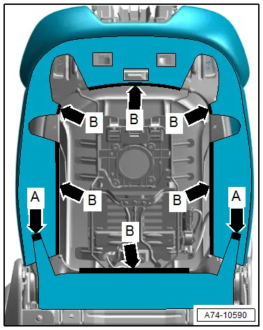
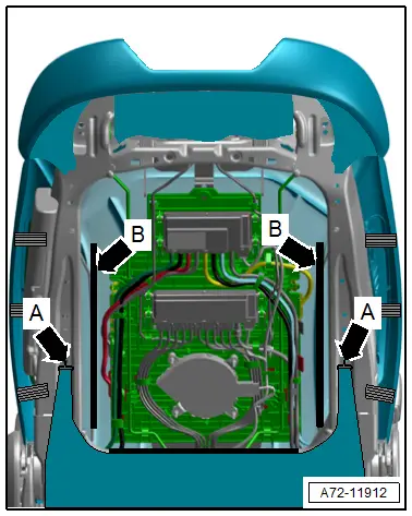
- Disengage the hooks on the sides of the backrest frame -arrows A-.
- Disengage the molding on the backrest frame -arrows B-.
- Remove the front thorax airbag. Refer to → Chapter "Front Thorax Airbag with Igniter, Removing and Installing".
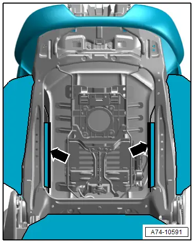
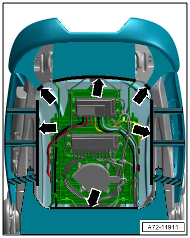
- Disengage the inner molding on the wire frame -arrows-.
- Loosen the cover with the cushion from the backrest frame and remove forward carefully.
Installing
 WARNING
- Follow all safety precautions when working on pyrotechnic components. Refer to → Chapter "Safety Precautions for Pyrotechnic Components".
- Before handling pyrotechnic components (for example, connecting the connector), the person handling it must "discharge static electricity". This can be done by briefly touching the door striker pin, for example.
- Observe all measures when installing the front seat. Refer to → Chapter "Front Seat, Removing and Installing".
Install in reverse order of removal.
Installation notes, for example tightening specifications, replacing components. Refer to → Chapter "Overview - Backrest Cover and Cushion".
Backrest Cover and Cushion, Removing and Installing, Seat with Pneumatic Components
Special tools and workshop equipment required
- Pry Lever -80-200-
- Trim Removal Wedge -3409-
Removing
 WARNING
Before handling pyrotechnic components (for example, disconnecting the connector), the person handling it must "discharge static electricity". This can be done by briefly touching the door striker pin, for example.
- Remove the front seat. Refer to → Chapter "Front Seat, Removing and Installing".
- Fasten the front seat on the -VAS6136-. Refer to → Chapter "Front Seat, Mounting on Fixture for Seat Repair".
- Remove the headrest. Refer to → Chapter "Headrest, Removing and Installing, Headrest with Height and Angle Adjuster".
- Remove the backrest cover. Refer to → Chapter "Backrest Cover, Removing and Installing".
- Remove the front backrest fan. Refer to → Chapter "Backrest Fan, Removing and Installing".
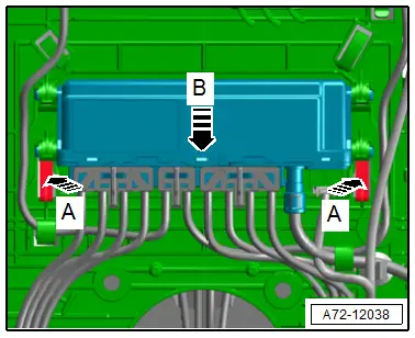
- Disengage the Valve Block 2 in Driver Seat - N476-/ Valve Block 2 in Front Passenger Seat -N478- from the module carrier -arrow B- by pressing the release buttons -arrows A-.
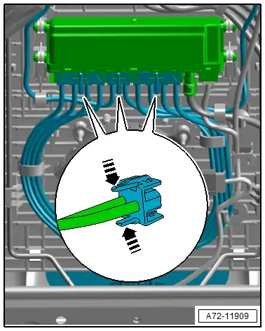
- Altogether, remove 3 pneumatic line connectors form the Valve Block 2 in Driver Seat -N476-/ Valve Block 2 in Front Passenger Seat -N478- by pressing the release buttons in direction of -arrows-.
- Pull the pneumatic lines forward and through.
- Disconnect the backrest heating wiring harness on the seat pan and free it up.
- Disengage the lower, upper and side molding from the backrest frame -arrows-.
- Remove the front thorax airbag. Refer to → Chapter "Front Thorax Airbag with Igniter, Removing and Installing".
- Disengage the hooks on the sides of the backrest frame -arrows A-.
- Disengage the inner molding on the wire bracket -arrows B-.
- Loosen the cover with the cushion from the backrest frame and remove forward carefully.
Installing
 WARNING
- Follow all safety precautions when working on pyrotechnic components. Refer to → Chapter "Safety Precautions for Pyrotechnic Components".
- Before handling pyrotechnic components (for example, connecting the connector), the person handling it must "discharge static electricity". This can be done by briefly touching the door striker pin, for example.
- Observe all measures when installing the front seat. Refer to → Chapter "Front Seat, Removing and Installing".
Install in reverse order of removal.
Information for installation: for example, tightening specifications, replacing body parts. Refer to → Chapter "Overview - Backrest Cover and Cushion" and → Chapter "Overview - Pneumatic System".

