Audi Q7: Charge Air System
Overview - Charge Air System
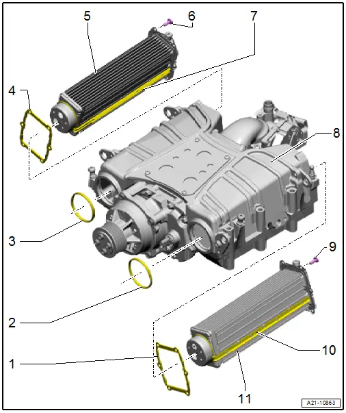
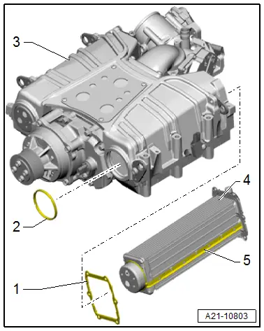
1 - Seal
- Replace after removing
2 - O-Ring
- Replace after removing
- Coat with engine oil when installing the charge air cooler
3 - O-Ring
- Replace after removing
- Coat with engine oil when installing the charge air cooler
4 - Seal
- Replace after removing
5 - Right Charge Air Cooler
- Removing and installing. Refer to → Chapter "Charge Air Cooler, Removing and Installing".
6 - Bolt
- 10 Nm
- Replace after removing
- Self-locking
7 - Seal
- Not available separately.
- May not be removed from the charge air cooler
- Coat with engine oil when installing the charge air cooler
8 - Supercharger Housing
9 - Bolt
- 10 Nm
- Replace after removing
- Self-locking
10 - Seal
- Not available separately.
- May not be removed from the charge air cooler
- Coat with engine oil when installing the charge air cooler
11 - Left Charge Air Cooler
- Removing and installing. Refer to → Chapter "Charge Air Cooler, Removing and Installing".
Overview - Charge Air Hose Connections
 Note
Note
- The hose connections as well as air duct pipes and hoses must be free of oil and grease before installing.
- Secure all hose connections with hose clamps that match the ones used in series production. Refer to the Parts Catalog.
- In order to be able to securely mount the air duct hoses on their connections, spray the bolts on the previously used screw-type clamps with rust remover before installing.
Tightening specification for
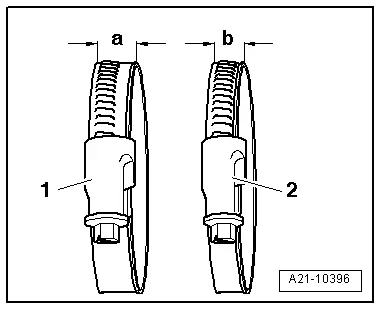
1 - Hose clamp -a- = 13 mm wide: 5.5 Nm
2 - Hose clamp -b- = 9 mm wide: 3.4 Nm
Charge Air Cooler, Removing and Installing
Special tools and workshop equipment required
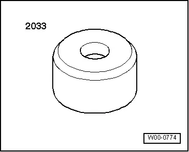
- Arbor -2033-
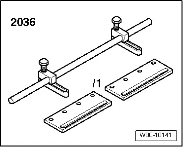
- Seal Installer - Valve Stem Seal Tool -2036-
- Tire pry lever, commercially available or the Pry Lever -VAG1942-
 Caution
This procedure contains mandatory replaceable parts. Refer to component overview prior to starting procedure.
Mandatory Replacement Parts
- Bolts - Charged air coolers
- O-rings - Charged air coolers
- Seals - Charged air coolers
Removing
- Supercharger secured on the Engine and Gearbox Bracket -VAS6095A- for repair work. Refer to → Chapter "Supercharger, Securing to Engine/Transmission Holder for Repair Work".
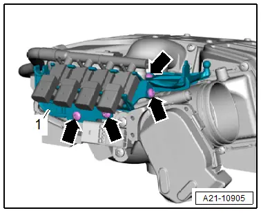
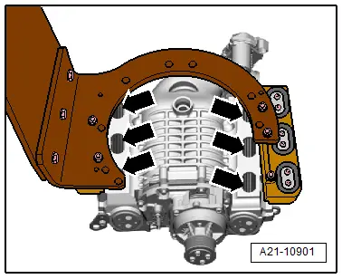
- Remove the bolts -arrows-, and remove the bracket -1- with the bypass valves.
Left Charge Air Cooler:
- Remove the charge air pressure sensor/intake manifold temperature sensor. Refer to → Chapter "Charge Air Pressure Sensor/Intake Manifold Temperature Sensor, Removing and Installing".
Right Charge Air Cooler:
- Remove the Throttle Valve Control Module -J338-. Refer to → Chapter "Throttle Valve Control Module -J338-, Removing and Installing".
- Remove the charge air pressure sensor/intake manifold temperature sensor. Refer to → Chapter "Charge Air Pressure Sensor/Intake Manifold Temperature Sensor, Removing and Installing".
Continuation for Both Sides:
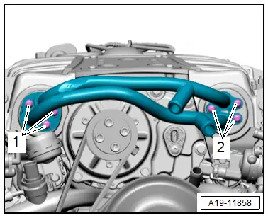
- Remove the bolts -1 and 2- and the coolant pipes from the compressor.
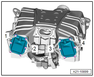
- Remove the charge air cooler bolts on the left -1 and 2- and right -3 and 4-.
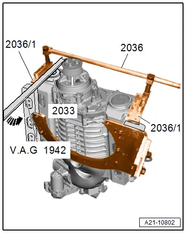
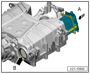
- Attach the Seal Installer - Valve Stem Seal Tool -2036- with the Seal Installer - Valve Stem Seal Tool Adapter Plates -2036/1- to the supercharger as illustrated.
- Position the Arbor -2033- on the front of the charge air cooler.
- Slowly remove the charge air cooler with even pressure from the supercharger housing using the Tire Pry Lever -VAG1942-.
Installing
 Note
Note
- Replace the seals, O-rings and self-locking screws after removing.
- Always clean the threaded holes inside the supercharger housing with a thread tap before assembling.
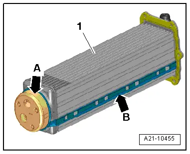
- Check the seal -5- on the charge air cooler -4-.
- The seal must not be cracked or damaged.
- Slide the seal -1- onto the charge air cooler.
- Insert the O-ring -2- into the opening in the supercharger housing -3-.
- Coat the sealing surface -arrow A- and the charge air cooler seal -arrow B--1- with engine oil.
- Coat the inner sealing surface inside the supercharger housing with engine oil.
- Make sure the seals are opposite the openings in the supercharger housing when installing the charge air cooler -arrows-.
 Note
Note
Holding the supercharger housing perpendicular in the Engine and Gearbox Bracket -VAS6095A- makes it easier to install and remove the charge air cooler.
 Caution
Danger of causing damage to the charge air cooler.
Install the charge air cooler by hand only.
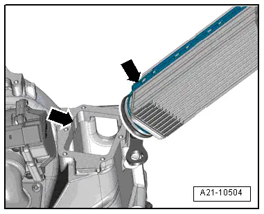
- Install the charge air cooler all the way into the supercharger housing by hand in direction of -arrow A-. When doing this, let the front of the charge air cooler slide into the hole -arrow B- inside the supercharger housing.
- Manually guide the charge air cooler by hand through the supercharger housing openings -arrows-, if necessary.
- As soon as it is possible, install the two bolts loosely by hand to help guide the charge air cooler.
 Caution
Danger of causing damage to the charge air cooler.
- The charge air cooler may not be installed by using the bolts.
- Install the charge air cooler by hand only until there is maximum 1 mm between the sealing flange and the seal and the supercharger housing. Only then should the bolts be tightened as follows:
- Tighten the bolts for the left -1 and 2- and right -3 and 4- charge air coolers in a diagonal sequence and in small steps.
Installation is performed in reverse order of removal, while noting the following:
- Install the coolant pipes to the supercharger. Refer to → Chapter "Supercharger Coolant Pipes, Removing and Installing".
- Install the Throttle Valve Control Module -J338-. Refer to → Chapter "Throttle Valve Control Module -J338-, Removing and Installing".
- Install the charge air pressure sensor/intake manifold temperature sensor. Refer to → Chapter "Charge Air Pressure Sensor/Intake Manifold Temperature Sensor, Removing and Installing".
- Check the supercharger for leaks. Refer to → Chapter "Supercharger, Checking for Leaks".

Tightening Specifications
- Refer to → Chapter "Overview - Charge Air System"
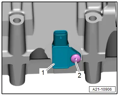
Charge Air Pressure Sensor/Intake Manifold Temperature Sensor, Removing and Installing
 Caution
This procedure contains mandatory replaceable parts. Refer to component overview prior to starting procedure.
Mandatory Replacement Parts
- O-ring - Charge Air Pressure Sensor/Intake Manifold Temperature Sensor
Removing
- Remove the supercharger. Refer to → Chapter "Supercharger, Removing and Installing".
- Remove the bolt -2- and remove the charge air pressure sensor/intake manifold temperature sensor -1-.
Installing
Install in reverse order of removal and note the following:
 Note
Note
- Replace the self-locking screws and O-ring after removal.
- Clean the threaded holes for the charge air pressure sensor inside the supercharger housing with a thread tap before assembling.
- Install the supercharger. Refer to → Chapter "Supercharger, Removing and Installing".
Tightening Specifications
- Refer to → Chapter "Overview - Supercharger"
Special Tools
Special tools and workshop equipment required
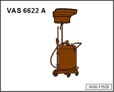
- Used Oil Collection and Extraction Unit -SMN372500-
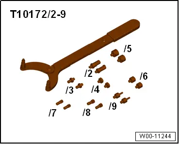
- Counterhold - Multiple Use -T10172A- with Counterhold - Kit - Adapter 5 -T10172/5-
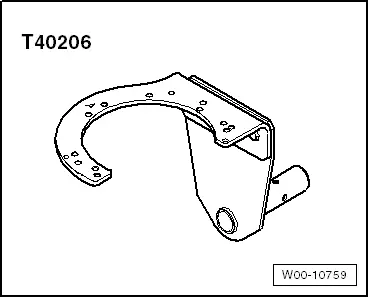
- Gearbox Support -T40206- with -T40206/1-
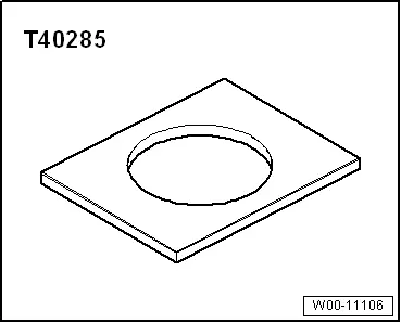
- Plate -T40285-
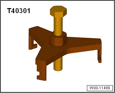
- Clutch Module Puller -T40301-
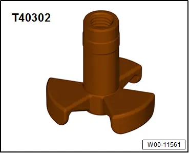
- Clutch Module Centering Device -T40302-
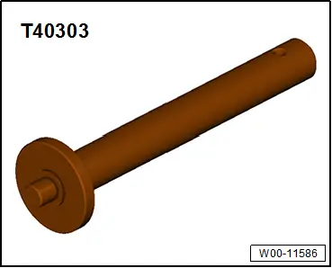
- Thrust Piece -T40303-
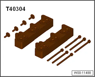
- Supercharger Module Support -T40304-
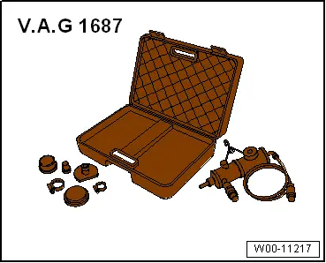
- Turbo System Tester Kit Adapter - VAG1687/4-, T urbo System Tester Kit - Adapter 10 -VAG1687/10-, Turbo System Tester Kit - Adapter 13-1 -VAG1687/13-1- and Turbo System Tester Kit - Adapter 13-2 -VAG1687/13-2-
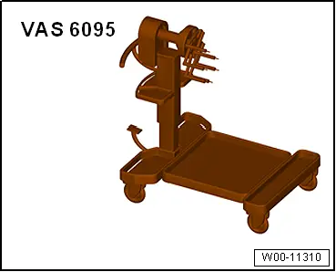
- Engine and Gearbox Bracket -VAS6095A-
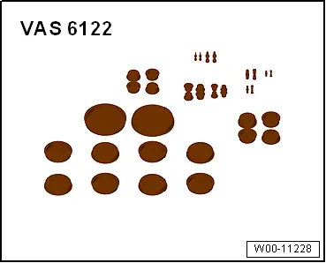
- Engine Bung Set -VAS6122-
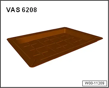
- Container of the Coolant Collection System -VAS5014- or the Shop Crane - Drip Tray -VAS6208-
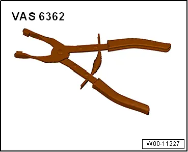
- Hose Clip Pliers -VAS6362-
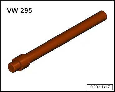
- Bearing/Bushing Installer - Multiple Use -VW295-
- Arbor -2033-
- Seal Installer - Valve Stem Seal Tool -2036-
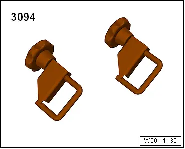
- Hose Clamps - Up To 25mm -3094-
- Bearing Installer - Wheel Bearing -3144-
- Turbo System Tester Kit -VAG1687-
- Test Adapter For Compressor Module -VAS6909A-
- Internal Puller -VAS501001-
- Tire pry lever, commercially available or the -VAG1942-