Audi Q7: Component Location Overview - Luggage Compartment Trim Panels
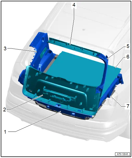
1 - Lock Carrier Trim
- Overview. Refer to → Chapter "Overview - Luggage Compartment Floor".
2 - Rear Lid Lower Trim Panel
- Overview. Refer to → Chapter "Overview - Rear Lid Lower Trim Panel".
3 - Luggage Compartment Side Trim Panel
- Overview. Refer to → Chapter "Overview - Luggage Compartment Side Trim Panel".
4 - Rear Lid Upper Trim Panel
- Overview. Refer to → Chapter "Overview - Rear Lid Upper Trim Panel".
5 - Rear Lid Side Trim Panel
- Overview. Refer to → Chapter "Overview - Rear Lid Upper Trim Panel".
6 - Luggage Compartment Floor
- Overview. Refer to → Chapter "Overview - Luggage Compartment Floor".
7 - Luggage Compartment Floor Support
- Overview. Refer to → Chapter "Overview - Luggage Compartment Floor".
Overview - Luggage Compartment Side Trim Panel
Overview - Luggage Compartment Side Trim Panel, Vehicles without High-Voltage System
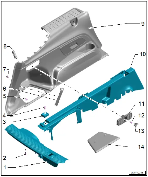
1 - Lock Carrier Trim Panel
- Removing and Installing. Refer to → Chapter "Lock Carrier Trim Panel, Removing and Installing".
- Must grip into the pins
- Press on until it engages audibly
- Stretch the rear lid seal lip
2 - Clip
- Quantity: 6
- Insert in the trim panel
- Remove any remaining clips from the mounting point using the Omega Clip Tool -T40280- and use them to install the trim.
- Replace damaged or deformed clips
3 - Tie Down
- Quantity: 2 each
- Removing and Installing. Refer to → Chapter "Tie Down, Removing and Installing".
4 - Bolt
- 20 Nm
- Quantity: 2 each
5 - Clip
- Quantity: 2
- Insert in the trim panel
- Replace damaged or deformed clips
6 - Luggage Compartment Lamp
- Removing and Installing. Refer to → Electrical Equipment; Rep. Gr.96; Lamps; Component Location Overview - Luggage Compartment Lamps.
7 - Clip
- Quantity: 4
- Insert in the trim panel
- Remove any remaining clips from the mounting point using the Omega Clip Tool -T40280- and use them to install the trim.
- Replace damaged or deformed clips
8 - Socket
- Removing and installing.
9 - Luggage Compartment Side Trim Panel
- Removing and Installing. Refer to → Chapter "Luggage Compartment Side Trim Panel, Removing and Installing, Vehicle without High-Voltage System".
- Press on until it engages audibly
- Stretch the rear lid seal lip
10 - Luggage Compartment Floor Support
- Removing and Installing. Refer to → Chapter "Luggage Compartment Support, Removing and Installing".
11 - Control Unit with Button
- Removing and Installing. Refer to → Electrical Equipment; Rep. Gr.96; Controls; Component Location Overview - Luggage Compartment Controls.
12 - Bolt
- Tightening specification. Refer to → Electrical Equipment; Rep. Gr.96; Controls; Component Location Overview - Luggage Compartment Controls
13 - Cap
14 - Service Cover
- Insert in the trim panel and press on it until it engages.
Overview - Luggage Compartment Side Trim Panel, Vehicles with High-Voltage System
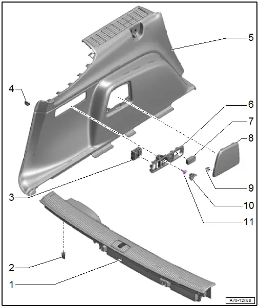
1 - Lock Carrier Trim Panel
- Removing and Installing. Refer to → Chapter "Lock Carrier Trim Panel, Removing and Installing".
- must grip into the pins
- Press on until it engages audibly
- Stretch the rear lid seal lip
2 - Clip
- Quantity: 6
- Insert in the trim panel
- Remove any remaining clips from the mounting point using the Omega Clip Tool -T40280- and use them to install the trim.
- Replace damaged or deformed clips
3 - Trailer Hitch Control Unit
- Removing and Installing. Refer to → Electrical Equipment; Rep. Gr.96; Controls; Component Location Overview - Luggage Compartment Controls.
4 - Clip
- Quantity: 4
- Insert in the trim panel
- Remove any remaining clips from the mounting point using the Omega Clip Tool -T40280- and use them to install the trim.
- Replace damaged or deformed clips
5 - Luggage Compartment Side Trim Panel
- Removing and Installing. Refer to → Chapter "Luggage Compartment Side Trim Panel, Removing and Installing, Vehicle with High-Voltage System".
- Press on until it engages audibly
- Stretch the rear lid seal lip
6 - Control Unit Frame
- Removing and Installing. Refer to → Electrical Equipment; Rep. Gr.96; Controls; Component Location Overview - Luggage Compartment Controls.
7 - Luggage Compartment Lamp
- Removing and Installing. Refer to → Electrical Equipment; Rep. Gr.96; Lamps; Component Location Overview - Luggage Compartment Lamps.
8 - Service Cover
- Insert in the trim panel and press on it until it engages.
9 - Clip
- Quantity: 2
- Insert in the trim panel
- Replace damaged or deformed clips
10 - Cap
11 - Bolt
- Tightening specification. Refer to → Electrical Equipment; Rep. Gr.96; Controls; Component Location Overview - Luggage Compartment Controls

