Audi Q7: Component Location Overview - Pneumatic System
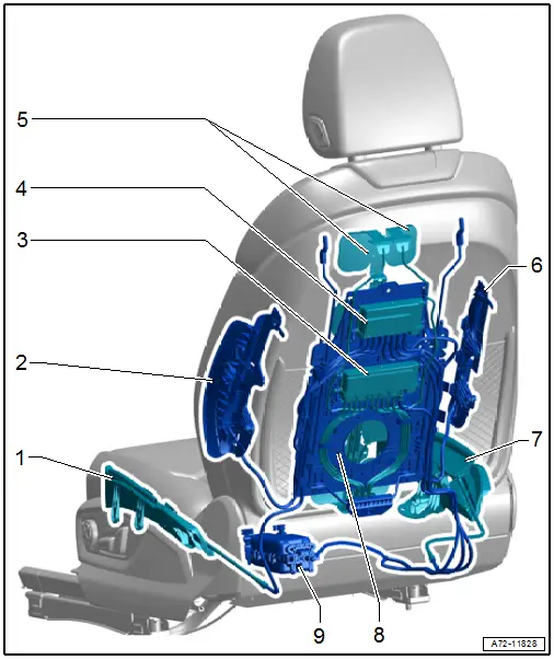
1 - Left Seat Bolster Inflation Adjuster
- Overview. Refer to → Chapter "Overview - Pneumatic System, Module Carrier/Lumbar Support/Seat Bolster Adjuster".
2 - Left Backrest Bolster Inflation Adjuster
- Overview. Refer to → Chapter "Overview - Pneumatic System, Module Carrier/Lumbar Support/Seat Bolster Adjuster".
3 - Valve Block 2 in Driver Seat -N476-
- Front passenger side: Valve Block 2 in Front Passenger Seat -N478-
- For massage mat
- Overview. Refer to → Chapter "Overview - Pneumatic System, Massage Mat".
4 - Valve Block 1 in Driver Seat -N475-
- Front passenger side: Valve Block 1 in Front Passenger Seat -N477-
- For lumbar support and side adjuster
- Overview. Refer to → Chapter "Overview - Pneumatic System, Module Carrier/Lumbar Support/Seat Bolster Adjuster".
5 - Massage Mat
- Overview. Refer to → Chapter "Overview - Pneumatic System, Massage Mat".
6 - Right Backrest Bolster Inflation Adjuster
- Overview. Refer to → Chapter "Overview - Pneumatic System, Module Carrier/Lumbar Support/Seat Bolster Adjuster".
7 - Right Seat Bolster Inflation Adjuster
- Overview. Refer to → Chapter "Overview - Pneumatic System, Module Carrier/Lumbar Support/Seat Bolster Adjuster".
8 - Module Carrier, Lumbar Support Air Cushion
- Overview. Refer to → Chapter "Overview - Pneumatic System, Module Carrier/Lumbar Support/Seat Bolster Adjuster".
9 - Driver Multi-Contour Seat Compressor -V439- with integrated Driver Multi-Contour Seat Control Module -J873-
- Front passenger side: Front Passenger Multi-Contour Seat Compressor -V440- with integrated Front Passenger Multi-Contour Seat Control Module -J872-
- Overview. Refer to → Chapter "Overview - Pneumatic System, Compressor".
Connection Diagram - Pneumatic System
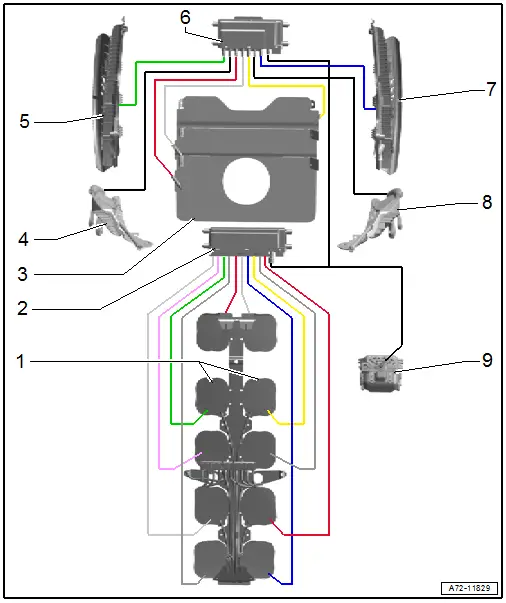
1 - Massage Mat
- in the cushion
2 - Valve Block 2 in Driver Seat -N476-
- Front passenger side: Valve Block 2 in Front Passenger Seat -N478-
- for massage mat
3 - Module Carrier with Air Cushions for Lumbar Support
4 - Left Seat Bolster Inflation Adjuster
5 - Left Backrest Bolster Inflation Adjuster
6 - Valve Block 1 in Driver Seat -N475-
- Front passenger side: Valve Block 1 in Front Passenger Seat -N477-
- for lumbar support and side adjuster
7 - Right Backrest Bolster Inflation Adjuster
8 - Right Seat Bolster Inflation Adjuster
9 - Driver Multi-Contour Seat Compressor -V439-
- Front passenger side: Front Passenger Multi-Contour Seat Compressor -V440-

