Audi Q7: Cover, Removing and Installing
Special tools and workshop equipment required
- Roller -3356-
- Wiring Harness Repair Set - Hot Air Blower -VAS1978/14A-
- Wedge Set -T10383-
- Cleaning Solution -D 009 401 04-
- Applicator -D 009 500 25-
- Bonding Agent -D 355 205 A2-
- Plastic Primer -D 366 PR A1-
Door Cover, Removing and Installing, Front
 Caution
This procedure contains mandatory replaceable parts. Refer to component overview prior to starting procedure.
Special tools and equipment. Refer to → Chapter "Cover, Removing and Installing".
Removing
- Open the door.
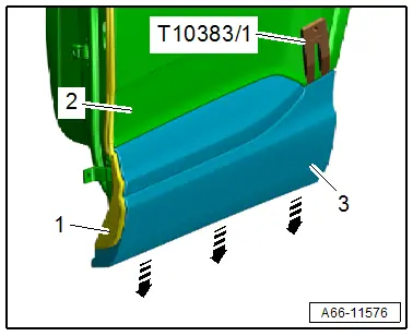
- Loosen the lower seam seal -1- from the bonding to the door cover -3-.
- Carefully warm the door cover using the -VAG1416- and pry using the -T10383/1- from the door -2- and disengage downward -arrows-.
Installing
Install in reverse order of removal and note the following:
- The vehicle and the cover must be at room temperature.
- The adhesive surfaces must be free of dirt and grease.
- If the Bonding Agent -D 355 205 A2- dries longer than 3 hours, then it must be primed again.
Installation preparation for reinstalling painted covers:
- Remove the adhesive residue completely from the cover.
- Clean the adhesive surface on the plastic side using the Cleaning Solution -D 009 401 04-.
- Apply the Plastic Primer -D 366 PR A1- to the adhesive surface on the cover and let it dry.
- Apply double-sided tape to the same location on the cover. Refer to Parts Catalog
Continuation:
- Clean the adhesive surface on the paint side using the Cleaning Solution -D 009 401 04-.
- Apply Bonding Agent -D 355 205 A2- to the adhesive surface on the paint side using the Applicator -D 009 500 25- and let it dry.
- Fold back the ends of the protective film, or attach the pulling aids -3 and 5- to the protective film.
- Remove the protective film on the pulling aids from the adhesive tape -2, 4 and 6-.
- Engage the doo cover -1- on the bottom of the door -7- and align via the locating pin.
- Press the door cover on until it audibly engages.
- Press on the door cover in the area of the adhesive surface with the -3356-.
- Vehicle resting time is at least one hour at room temperature.
- It is durable after at least 24 hours.
- Install the seam seal. Refer to → Chapter "Seam Seal, Removing and Installing".
Door Cover, Removing and Installing, Rear
 Caution
This procedure contains mandatory replaceable parts. Refer to component overview prior to starting procedure.
Special tools and equipment. Refer to → Chapter "Cover, Removing and Installing".
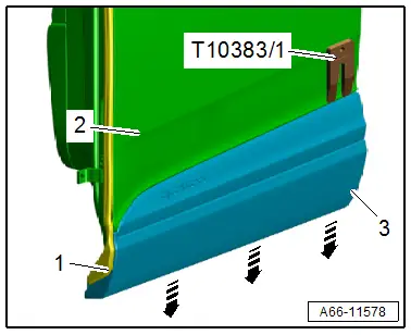
Removing
- Open the door.
- Remove the seam seal -1- from the door cover -3-.
- Carefully warm the door cover using the -VAG1416- and pry using the -T10383/1- from the door -2- and disengage downward -arrows-.
Installing
Install in reverse order of removal and note the following:
- The vehicle and the cover must be at room temperature.
- The adhesive surfaces must be free of dirt and grease.
- If the Bonding Agent -D 355 205 A2- dries longer than 3 hours, then it must be primed again.
Installation Preparation for Reinstalling Painted Covers:
- Remove the adhesive residue completely from the cover.
- Clean the adhesive surface on the plastic side using the Cleaning Solution -D 009 401 04-.
- Apply the Plastic Primer -D 366 PR A1- to the adhesive surface on the cover and let it dry.
- Apply double-sided tape to the same location on the cover. Refer to Parts Catalog
Continuation:
- Clean the adhesive surface on the paint side using the Cleaning Solution -D 009 401 04-.
- Apply Bonding Agent -D 355 205 A2- to the adhesive surface on the paint side using the Applicator -D 009 500 25- and let it dry.
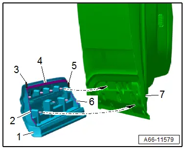
- Fold back the end of the protective film, or attach the pulling aids -3 and 5- to the protective film.
- Remove the protective film on the pulling aids from the adhesive tape -2, 4 and 6-.
- Engage the doo cover -1- on the bottom of the door -7- and align via the locating pin.
- Press the door cover on until it audibly engages.
- Press on the door cover in the area of the adhesive surface with the -3356-.
- Vehicle resting time is at least one hour at room temperature.
- It is durable after at least 24 hours.
Sill Panel Trim, Removing and Installing
 Caution
This procedure contains mandatory replaceable parts. Refer to component overview prior to starting procedure. Refer to → Chapter "Overview - Sill Panel Trim"
Special tools and workshop equipment required
- Roller -3356-
- Trim Removal Wedge -3409-
- Wiring Harness Repair Set - Hot Air Blower -VAS1978/14A-
- Cleaning Solution -D 009 401 04-
- Applicator -D 009 500 25-
- Bonding Agent -D 355 205 A2-
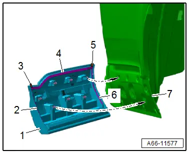
Removing
Versions with Illuminated Sill Panel:
- Remove the front sill panel. Refer to → Body Interior; Rep. Gr.70; Vehicle Interior Trim Panels; Sill Panel, Removing and Installing.
- Lift the carpet slightly and disconnect the connector -3-.
- Free up the wire by slightly pulling the seal -2- away from the body flange.
Continuation for All Vehicles:
- Carefully warm up the sill panel trim -1- using the -VAS1978/14A-.
- Carefully pry the sill panel trim from the side sill -arrow- using the -3409-. Do not damage the paint coat while doing so.
Installing
- The vehicle and the trim must be at room temperature.
- The adhesive surfaces must be free of dirt and grease.
- If the Bonding Agent -D 355 205 A2- dries longer than 3 hours, then it must be primed again.
Installation Preparation for Reinstalling Illuminated Sill Panel Trims:
- Remove any adhesive residue completely from the trim.
- Clean the adhesive surface on the plastic side using the Cleaning Solution -D 009 401 04-.
- Apply the Plastic Primer -D 366 PR A1- to the adhesive surface on the cover and let it dry.
- Apply double-sided tape to the same location on the trim. Refer to Parts Catalog
Continuation:
- Clean the adhesive surface on the paint side using the Cleaning Solution -D 009 401 04-.
- Apply Bonding Agent -D 355 205 A2- to the adhesive surface on the paint side using the Applicator -D 009 500 25- and let it dry.
- Remove the protective film from the adhesive tape -1 and 3-.
- Position the sill panel trim -2- over the pins on the side sill -arrows-.
- Push the sill panel trim onto the side sill using the -3356-.
- Vehicle resting time is at least 3.5 hours at room temperature.
Further installation is the reverse order of removal.
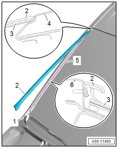
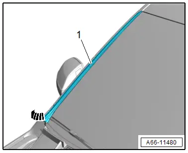
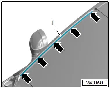
Drip Rail, Removing and Installing
Special tools and workshop equipment required
- Hand drill
- 5 mm drill bit
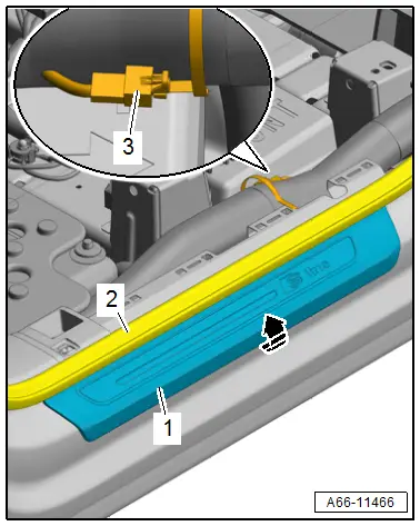
Drip Rail, Removing
- Starting at the bottom, carefully remove the drip rail -1- upward -arrow-.
Drip Rail Clamping Strip, Removing
- Drill out the rivet heads -arrows- and drive out the rivet shafts.
- Remove the clamping strip -1-.
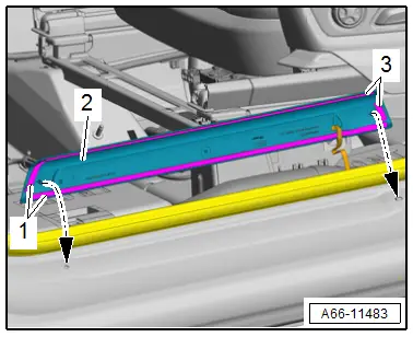
Installing
- Push in the drip rail -2- starting at the top in the retaining strip -5- and clip -1- all the way.
3 - Windshield
4 - Roof
6 - A-Pillar
Installation Instructions. Refer to → Chapter "Overview - Drip Rail".