Audi Q7: Floor Heat Shield, Removing and Installing
Plenum Chamber Bulkhead Heat Shield, Removing and Installing
Removing
- Remove the plenum chamber bulkhead. Refer to → Chapter "Plenum Chamber Bulkhead, Removing and Installing".
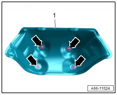
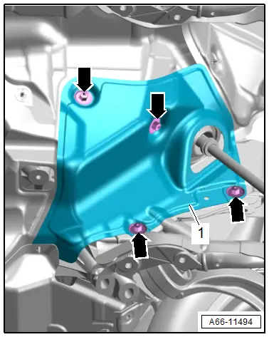
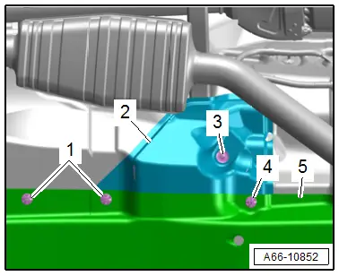
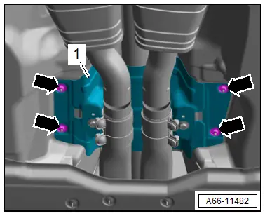
- Remove the nuts -arrows-.
- Remove the heat shield -1-.
Installing
Install in reverse order of removal.
Tightening Specifications
- Refer to → Chapter "Overview - Front Heat Shield"
Lower Plenum Chamber Bulkhead Heat Shield, Removing and Installing
Removing
- Remove the subframe crossbrace. Refer to → Suspension, Wheels, Steering; Rep. Gr.40; Subframe; Subframe Crossbrace, Removing and Installing.
- Remove the front muffler/front exhaust pipe. Refer to → Engine Mechanical; Rep. Gr.26; Exhaust Pipes/Mufflers; Overview - Muffler and → Engine Mechanical; Rep. Gr.26; Emissions Control System; Overview - Emissions Control System.
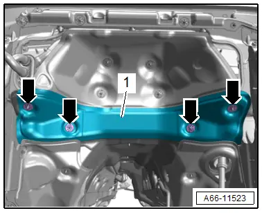
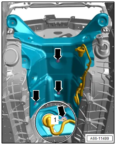
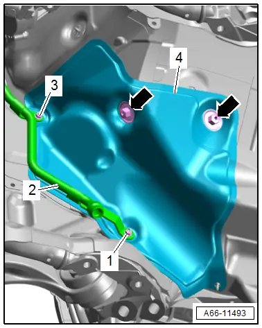
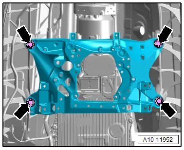
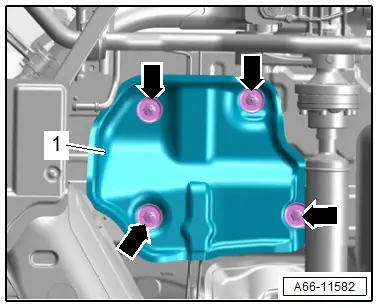
- Remove the lock washers -arrows-.
- Remove the heat shield -1- downward to the right.
Installing
Install in reverse order of removal.
Upper Front Tunnel Heat Shield, Removing and Installing
Special tools and workshop equipment required
- Engine and Gearbox Jack -VAS6931-
- Engine/Gearbox Jack - Gearbox Support -T10337-
Removing
- Remove the heat shield for the lower plenum chamber bulkhead. Refer to → Chapter "Lower Plenum Chamber Bulkhead Heat Shield, Removing and Installing".
- Vehicles with high-voltage system: remove the transmission. Refer to → 8-Speed Automatic Transmission; Rep. Gr.37; Transmission, Removing and Installing; Transmission, Removing.
- Remove the rear heat shield for the longitudinal member. Refer to → Chapter "Rear Longitudinal Member Heat Shield, Removing and Installing".
- Place the -T10337- on the -VAS6931- and position it at the bottom of the transmission.
 Note
Note
For reasons of clarity, the -T10337- is not shown.
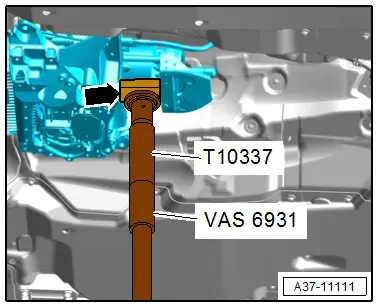
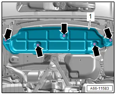
- Remove the tunnel crossmember bolts -arrows-.

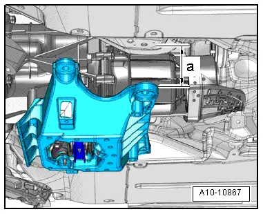
- Lower the engine/transmission assembly to dimension -a- using the -VAS6931-.
- Dimension -a- = maximum 40 mm.
- Remove the lock washers -arrows-.
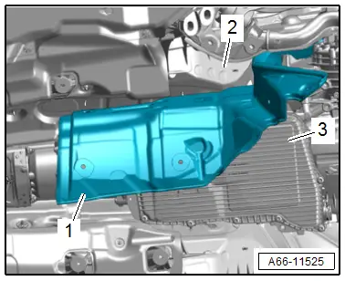
- Free up the wiring harness -1- on the left side of the vehicle.
- Remove the heat shield -1- to the lower right between the transmission -3- and body -2-.
Installing
Install in reverse order of removal and note the following:
Tightening Specifications
- Refer to → 8-Speed Automatic Transmission; Rep. Gr.37; Subframe Mount; Overview - Subframe Mount.
Front Longitudinal Member Heat Shield, Removing and Installing, Vehicles without High-Voltage System
Removing
- Remove the rear heat shield for the longitudinal member. Refer to → Chapter "Rear Longitudinal Member Heat Shield, Removing and Installing".
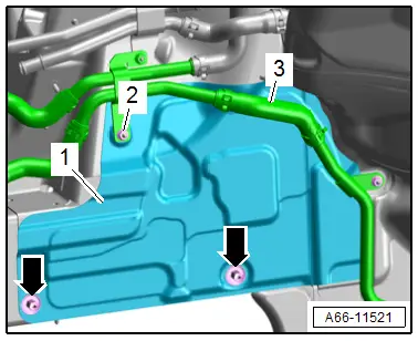
- Right side of the vehicle: remove the nut -2- and free up the coolant pipe -3-.
- Remove the nuts -arrows-.
- Remove the heat shield -1- downward to the toward the rear.
Installing
Install in reverse order of removal.
Tightening Specifications
- Refer to → Chapter "Overview - Front Heat Shield"
Front Longitudinal Member Heat Shield, Removing and Installing, Vehicles with High-Voltage System
Removing
- Vehicles with 6-cylinder engine: Remove the engine. Refer to → Engine Mechanical; Rep. Gr.10; Engine, Removing and Installing; Engine, Removing.
- Remove the rear heat shield for the longitudinal member. Refer to → Chapter "Rear Longitudinal Member Heat Shield, Removing and Installing".
- Remove the high-voltage battery coolant pump. Refer to → Engine Mechanical; Rep. Gr.19; Coolant Pump/Coolant Regulation; Electric Coolant Pump, Removing and Installing.
- Remove the coolant change-over valve 1. Refer to → Engine Mechanical; Rep. Gr.19; Coolant Pump/Coolant Regulation; Coolant Valves, Removing and Installing.
- Vehicles with 4-cylinder engine, right side of the vehicle: Remove the catalytic converter. Refer to → Engine Mechanical; Rep. Gr.26; Emissions Control System; Catalytic Converter, Removing and Installing.
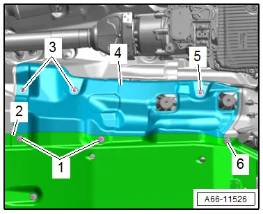
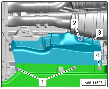
- Free up the coolant hose -1-.
- Remove the nuts -2 and 4-.
- Remove the bracket -3-.
- Right side of the vehicle: remove the nut -2, 4- and free up the coolant pipes -3-.
- Remove the nut -arrow-.
- Remove the heat shield -1- downward to the toward the rear.
Installing
Install in reverse order of removal.
Tightening Specifications
- Refer to → Chapter "Overview - Front Heat Shield"
- Refer to → Engine Mechanical; Rep. Gr.19; Coolant Pump/Coolant Regulation; Overview - Electric Coolant Pump.
Rear Longitudinal Member Heat Shield, Removing and Installing
Removing
- Vehicles with high-voltage system: remove the transmission. Refer to → 8-Speed Automatic Transmission; Rep. Gr.37; Transmission, Removing and Installing; Transmission, Removing.
- Remove the rear noise insulation. Refer to → Chapter "Noise Insulation, Removing and Installing, Rear".
- Remove the subframe crossbrace. Refer to → Suspension, Wheels, Steering; Rep. Gr.40; Subframe; Subframe Crossbrace, Removing and Installing.
Left Side of Vehicle:
- Remove the bolt -1-.
- Remove the universal joint -2- of the steering intermediate shaft from the steering gear -3- and push it together.
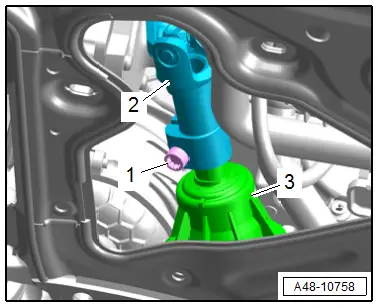
- Remove the nuts -arrows-.
- Remove the heat shield -1- downward.
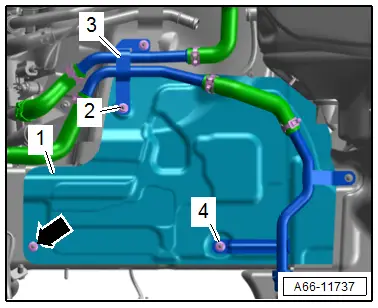
Right Side of Vehicle:
- Remove the front muffler/front exhaust pipe. Refer to → Engine Mechanical; Rep. Gr.26; Exhaust Pipes/Mufflers; Overview - Muffler and → Engine Mechanical; Rep. Gr.26; Emissions Control System; Overview - Emissions Control System.
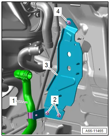
- Remove the nuts -1 and 3- and move the coolant line -2- to the side.
- Remove the nuts -arrows-.
- Remove the heat shield -4- downward.
Installing
Install in reverse order of removal and note the following:
- Install the steering intermediate shaft. Refer to → Suspension, Wheels Steering; Rep. Gr.48; Steering Column; Steering Intermediate Shaft, Removing and Installing.
Tightening Specifications
- Refer to → Chapter "Overview - Front Heat Shield"
Transmission Tunnel Heat Shield, Removing and Installing
Special tools and workshop equipment required
- Hose Clamps - Up To 25 mm -3094-
- Engine Bung Set -VAS6122-
- Container of the Coolant Collection System -VAS5014- or the Shop Crane - Drip Tray -VAS6208-
- Hose Clip Pliers -VAS6340-
Removing
- Remove the heat shield for the front tunnel. Refer to → Chapter "Heat Shield for Front Tunnel, Removing and Installing".
- Remove the heat shield for the rear tunnel. Refer to → Chapter "Heat Shield for Rear Tunnel, Removing and Installing".
Vehicles with Rear Heater and A/C Unit:
- Place the container of the -VAS5014- or the -VAS6208- underneath.
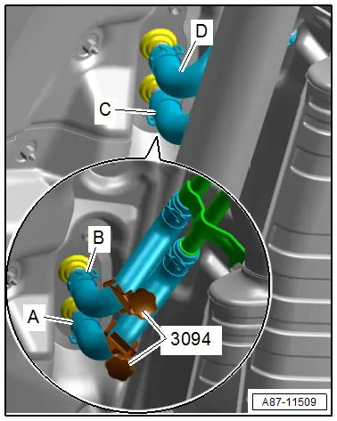
- Mark the layout of the coolant hoses -C and D- on the connections to the heat exchanger.
- Clamp off the coolant hoses using the -3094-.
- Loosen the clamps -A and B- and remove the coolant hoses.
- Seal open line connections at the connection point with clean plugs, for example from the -VAS6122-.
Continuation for all Vehicles:
- Remove the nut -1- and free up the cable holder.
- Free up the emergency release cable -6-.
- Remove the lock washer -2, 4, 5 and 7-.
- Remove the heat shield -3- for the transmission tunnel.

Installing
Install in reverse order of removal and note the following:
- Fill the coolant. Refer to → Engine Mechanical; Rep. Gr.19; Cooling System/Coolant; Coolant, Draining and Filling.
Tightening Specifications
- Refer to → Chapter "Overview - Rear Heat Shield"
Heat Shield for Front Tunnel Brace, Removing and Installing
Removing
- Remove the nuts -1 and 4- for the underbody trim panel -5- in the area of the heat shield.
- Remove the nut/screw -3-.
- Remove the heat shield -2-.
Installing
Install in reverse order of removal.
Tightening Specifications
- Refer to → Chapter "Overview - Rear Heat Shield"
- Refer to → Chapter "Overview - Underbody Trim Panels"
Heat Shield for Front Tunnel, Removing and Installing
Special tools and workshop equipment required
- Engine and Gearbox Jack -VAS6931-
- Engine/Gearbox Jack - Gearbox Support -T10337-
Removing
- Vehicles with gasoline engine: remove the front muffler on the corresponding side. Refer to → Engine Mechanical; Rep. Gr.26; Exhaust Pipes/Mufflers; Front Muffler, Removing and Installing.
- Vehicles with front tunnel brace: remove the heat shield for the front tunnel brace. Refer to → Chapter "Heat Shield for Front Tunnel Brace, Removing and Installing".
- Place the -T10337- on the -VAS6931- and position it at the bottom of the transmission.
 Note
Note
For reasons of clarity, the -T10337- is not shown.

- Remove the tunnel crossmember bolts -arrows-.
- Lower the engine/transmission assembly to dimension -a- using the -VAS6931-.
- Dimension -a- = maximum 40 mm.

- Remove the nuts -1 and 6- for the underbody trim panel -2- in the area of the heat shield.
- Remove the nuts -3 and 5-.
- Free up the heat shield -4- near the stud bolts.
- Remove heat shield.
Installing
Install in reverse order of removal and note the following:
- Make sure that the heat shield is pushed in behind the heat shield for the rear tunnel.
Tightening Specifications
- Refer to → Chapter "Overview - Rear Heat Shield"
- Refer to → Chapter "Overview - Underbody Trim Panels"
- Refer to → 8-Speed Automatic Transmission; Rep. Gr.37; Subframe Mount; Overview - Subframe Mount.
Heat Shield for Rear Tunnel, Removing and Installing
Removing
- Remove the heat shield for the front tunnel. Refer to → Chapter "Heat Shield for Front Tunnel, Removing and Installing".
- Detach the driveshaft heat shield. Refer to → Chapter "Driveshaft Heat Shield, Removing and Installing".
- Remove the nuts -1 and 4- from the underbody trim panel near the heat shield.
- Remove the nut -2-.
- Remove the rear heat shield -3-.
Installing
Install in reverse order of removal.
Tightening Specifications
- Refer to → Chapter "Overview - Rear Heat Shield"
- Refer to → Chapter "Overview - Underbody Trim Panels"
Driveshaft Heat Shield, Removing and Installing
Removing
- Remove the nuts -arrows-.
- Remove the exhaust system clamping sleeves. Refer to → Engine Mechanical; Rep. Gr.26; Exhaust Pipes/Mufflers; Overview - Muffler and → Engine Mechanical; Rep. Gr.26; Emissions Control System; Overview - Emissions Control System.
- Remove the heat shield -1- toward the front.
Installing
Install in reverse order of removal.
Tightening Specifications
- Refer to → Chapter "Overview - Rear Heat Shield"
Center Exhaust System Heat Shield, Removing and Installing
Special tools and workshop equipment required
- Engine and Gearbox Jack -VAS6931-
Removing
- Vehicles with gasoline engine: loosen the rear muffler mounting and center muffler and lower slightly using the -VAS6931-. Refer to → Engine Mechanical; Rep. Gr.26; Exhaust Pipes/Mufflers; Overview - Mufflers.
- Remove the nuts -arrows-.
- Remove the heat shield -1- past the exhaust system to the left.
Installing
Install in reverse order of removal.
Tightening Specifications
- Refer to → Chapter "Overview - Rear Heat Shield"
Rear Muffler Heat Shield, Removing and Installing
Special tools and workshop equipment required
- Engine and Gearbox Jack -VAS6931-
Removing
- Loosen the rear muffler mounting and lower it slightly using the -VAS6931-. Refer to → Engine Mechanical; Rep. Gr.26; Exhaust Pipes/Mufflers; Overview - Mufflers.
- Remove the nuts -arrows-.
- Remove the heat shield -1-.
Installing
Install in reverse order of removal.
Tightening Specifications
- Refer to → Chapter "Overview - Rear Heat Shield"

