Audi Q7: Underbody Trim Panel
Overview - Underbody Trim Panels
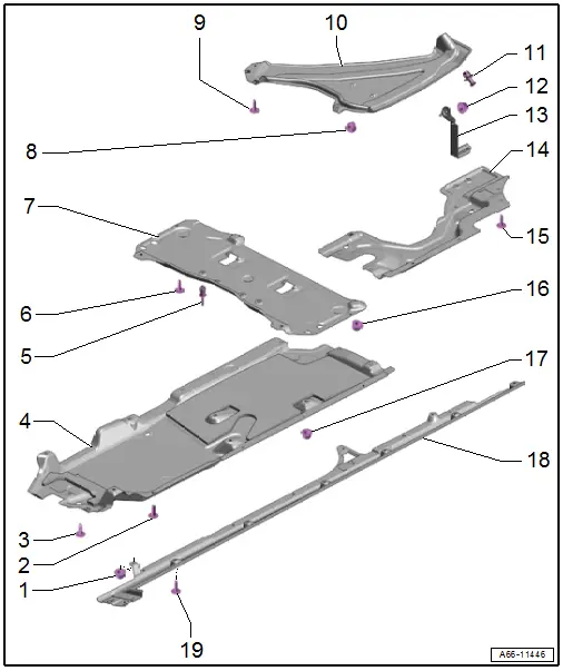
1 - Nut
- 2.5 Nm
- Quantity: 2
2 - Bolt
- 2.5 Nm
- Quantity: 4
3 - Bolt
- 6 Nm
4 - Front Underbody Panel
- There are different versions. Refer to the Parts Catalog.
- Removing and Installing. Refer to → Chapter "Underbody Trim Panel, Removing and Installing, Front".
5 - Expanding Rivet
- Quantity: 4
6 - Bolt
- 2.5 Nm
- Quantity: 2
7 - Center Underbody Trim Panel
- Removing and Installing. Refer to → Chapter "Underbody Trim Panel, Removing and Installing, Center".
8 - Nut
- 2.5 Nm
9 - Bolt
- 2.5 Nm
10 - Tank Underbody Trim Panel
- Removing and Installing. Refer to → Chapter "Underbody Trim Panel, Removing and Installing, Tank".
11 - Expanding Rivet
12 - Nut
- 4.5 Nm
13 - Bracket
- For the side underbody trim panel
14 - Rear Underbody Trim Panel
- Removing and Installing. Refer to → Chapter "Underbody Trim Panel, Removing and Installing, Rear".
15 - Bolt
- 2.5 Nm
- Quantity: 6
16 - Nut
- 2.5 Nm
- Quantity: 2
17 - Nut
- 2.5 Nm
- With fastener
- Quantity: 11
18 - Side Underbody Trim Panel
- Removing and Installing. Refer to → Chapter "Underbody Trim Panel, Removing and Installing, Side".
19 - Bolt
- 2.5 Nm
- Quantity: 6
Overview - Underbody Bracing
Overview - Tunnel Brace
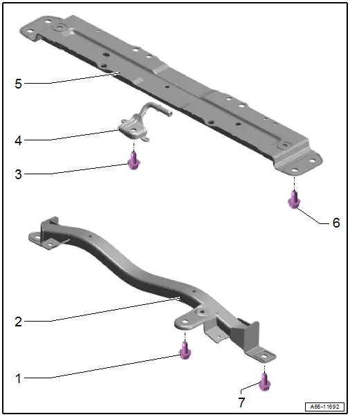
1 - Bolt
- 70 Nm
2 - Front Tunnel Brace
- Removing and Installing. Refer to → Chapter "Front Tunnel Brace, Removing and Installing".
3 - Bolt
- 49 Nm
4 - Mount
- For the center muffler
5 - Rear Tunnel Brace
- Removing and Installing. Refer to → Chapter "Rear Tunnel Brace, Removing and Installing".
6 - Bolt
- 49 Nm
- Quantity: 9
7 - Bolt
- 49 Nm
- Quantity: 2
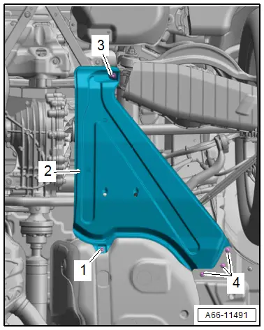
Overview - Diagonal Brace
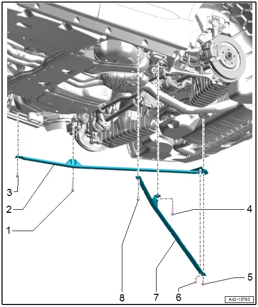
1 - Bolt
- Tightening specification. Refer to → Suspension, Wheels, Steering; Rep. Gr.42; Subframe; Overview - Subframe.
2 - Right Diagonal Brace
- Removing and Installing. Refer to → Chapter "Diagonal Braces, Removing and Installing".
3 - Bolt
- 49 Nm
4 - Bolt
- Tightening specification. Refer to → Suspension, Wheels, Steering; Rep. Gr.42; Subframe; Overview - Subframe.
5 - Bolt
- 49 Nm
6 - Bolt
- 25 Nm
7 - Left Diagonal Brace
- Removing and Installing. Refer to → Chapter "Diagonal Braces, Removing and Installing".
8 - Bolt
- 49 Nm
Overview - Impact Guard
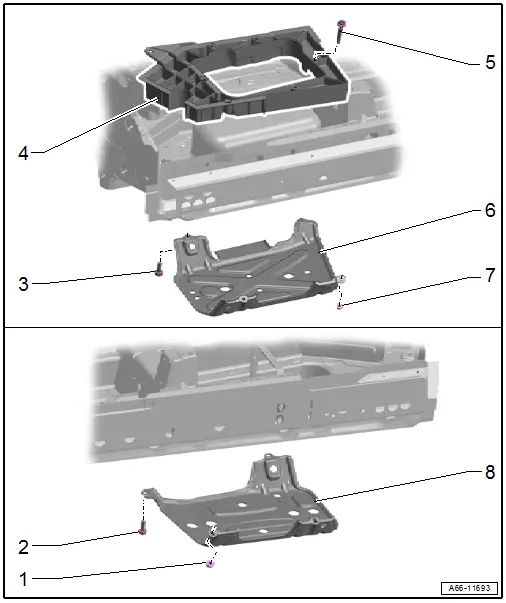
1 - Nut
- 25 Nm
- Quantity: 2
2 - Bolt
- 25 Nm
- Quantity: 2
3 - Bolt
- 25 Nm
- Quantity: 2
4 - Reinforcement
- For power electronics
5 - Bolt
- Quantity: 7
- 24 Nm
6 - Left Impact Guard
- Removing and Installing. Refer to → Chapter "Impact Guard, Removing and Installing".
7 - Nut
- 25 Nm
- Quantity: 2
8 - Right Impact Guard
- Removing and Installing. Refer to → Chapter "Impact Guard, Removing and Installing".
Underbody Trim Panels, Removing and Installing
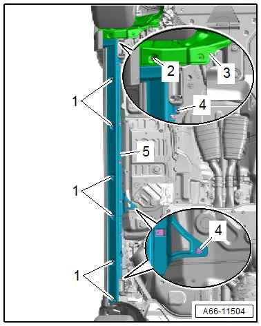
Underbody Trim Panel, Removing and Installing, Front
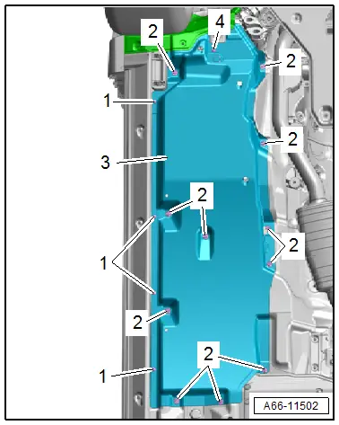
Removing
- Remove the left noise insulation. Refer to → Chapter "Noise Insulation, Removing and Installing, Left"
- Remove the nuts -2- and bolts -1 and 4-.
- Remove the front underbody trim panel -3-.
Installing
Install in reverse order of removal.
Tightening Specifications
- Refer to → Chapter "Overview - Underbody Trim Panels"
Underbody Trim Panel, Removing and Installing, Center
Removing
- Remove the expanding rivets -1-.
- Remove the nuts -3- and bolts -2-.
- Remove the center underbody trim panel -4-.
Installing
Install in reverse order of removal.
Tightening Specifications
- Refer to → Chapter "Overview - Underbody Trim Panels"
Underbody Trim Panel, Removing and Installing, Rear
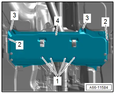
Removing
- Remove the expanding rivet -3-.
- Remove the nut -1- and bolts -4-.
- Remove the rear underbody trim panel -2-.
Installing
Install in reverse order of removal.
Tightening Specifications
- Refer to → Chapter "Overview - Underbody Trim Panels"
Underbody Trim Panel, Removing and Installing, Tank
Removing
- Remove the nuts -3- for the underbody trim panel -4-.
- Remove the bolts -1, 2 and 5-.
- Remove the tank underbody trim panel -6-.
Installing
Install in reverse order of removal.
Tightening Specifications
- Refer to → Chapter "Overview - Underbody Trim Panels"
Underbody Trim Panel, Removing and Installing, Side
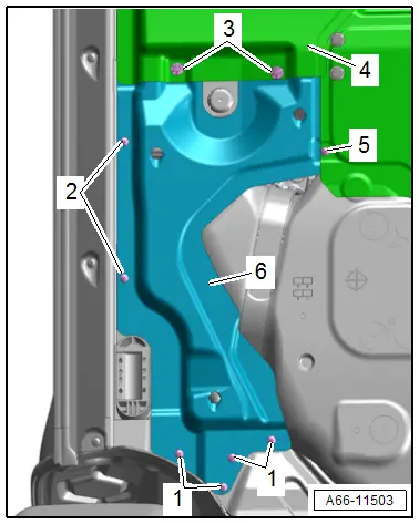
Removing
- Remove the front underbody panel. Refer to → Chapter "Underbody Trim Panel, Removing and Installing, Front".
- Remove the tank underbody trim panel. Refer to → Chapter "Underbody Trim Panel, Removing and Installing, Tank".
- Remove the nuts -4- and bolts -1 and 2-.
- Push the wheel housing liner -3- slightly to the side and remove the side underbody trim panel -5-.
Installing
Install in reverse order of removal.
Tightening Specifications
- Refer to → Chapter "Overview - Underbody Trim Panels"
- Refer to → Chapter "Overview - Front Wheel Housing Liner"
Tunnel Brace, Removing and Installing
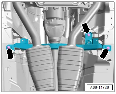
Front Tunnel Brace, Removing and Installing
Removing
- Remove the heat shield for the front tunnel brace. Refer to → Chapter "Heat Shield for Front Tunnel Brace, Removing and Installing".
- Remove the bolts -arrows-.
- Vehicles with TDI engine: remove the tunnel brace.
- Vehicles with gasoline engine: remove the exhaust system clamping sleeves. Refer to → Engine Mechanical; Rep. Gr.26; Exhaust Pipes/Mufflers; Overview - Muffler.
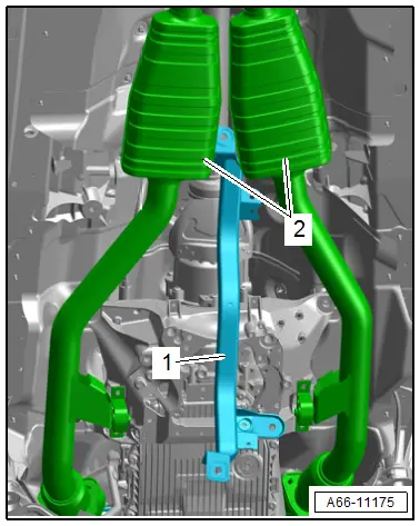
- Remove the tunnel brace -1- forward from between the center mufflers -2-.
Installing
Install in reverse order of removal.
Tightening Specifications
- Refer to → Chapter "Overview - Underbody Bracing"
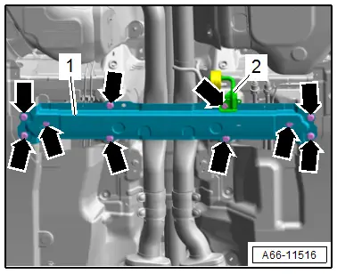
Rear Tunnel Brace, Removing and Installing
Removing
- Remove the center underbody panel. Refer to → Chapter "Underbody Trim Panel, Removing and Installing, Center".
- Remove the bolts -arrows-.
- Pivot the mounting -2- to the side and remove the tunnel brace -1-.
Installing
Install in reverse order of removal.
Tightening Specifications
- Refer to → Chapter "Overview - Underbody Bracing"
Diagonal Braces, Removing and Installing
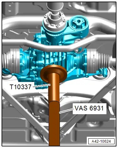
Special tools and workshop equipment required
- Engine and Gearbox Jack -VAS6931-
- Engine/Gearbox Jack - Gearbox Support -T10337-
Removing
- Remove the left and right underbody trim panel. Refer to → Chapter "Underbody Trim Panel, Removing and Installing, Side".
- Support the subframe using the -VAS6931- and -T10337-.
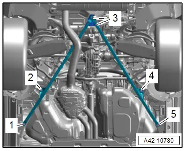
 CAUTION
Risk of damaging the thread by using an impact wrench.
- When installing, position the bolts by hand and screw in the first threads.
- Do not loosen or tighten the bolts with an impact wrench.
- Remove the bolts -1 to 5- and the diagonal brace.
- Re-install the bolts -2 and 4- all the way.
Installing
Install in reverse order of removal.
Tightening Specifications
- Refer to → Chapter "Overview - Underbody Bracing"
Impact Guard, Removing and Installing
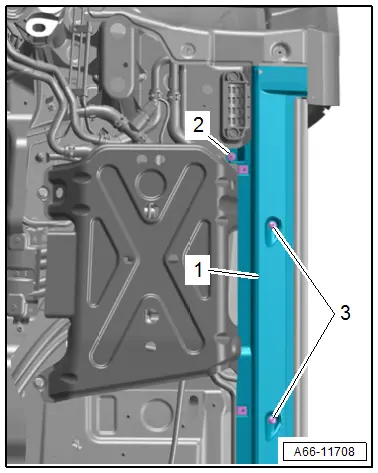
Removing
- Remove the front underbody panel. Refer to → Chapter "Underbody Trim Panel, Removing and Installing, Front".
- Right side of the vehicle: free up the front tunnel heat shield near the impact guard.
- Remove the nut -2- and bolts -3-, and push the underbody trim panel -1- slightly to the side.
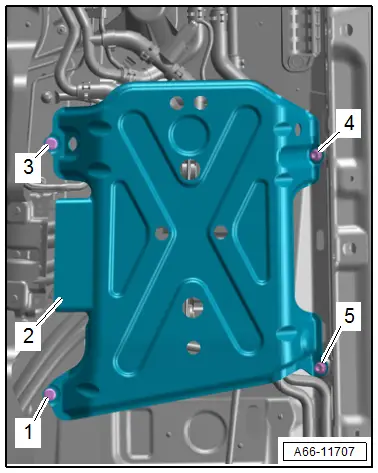
- Remove the nuts -4 and 5- and bolts -1 and 3-.
- Remove the impact guard -2-.
Installing
Install in reverse order of removal.
Tightening Specifications
- Refer to → Chapter "Overview - Underbody Trim Panels"
- Refer to → Chapter "Overview - Underbody Bracing"

