Audi Q7: Exterior Rearview Mirror
Overview - Exterior Rearview Mirror
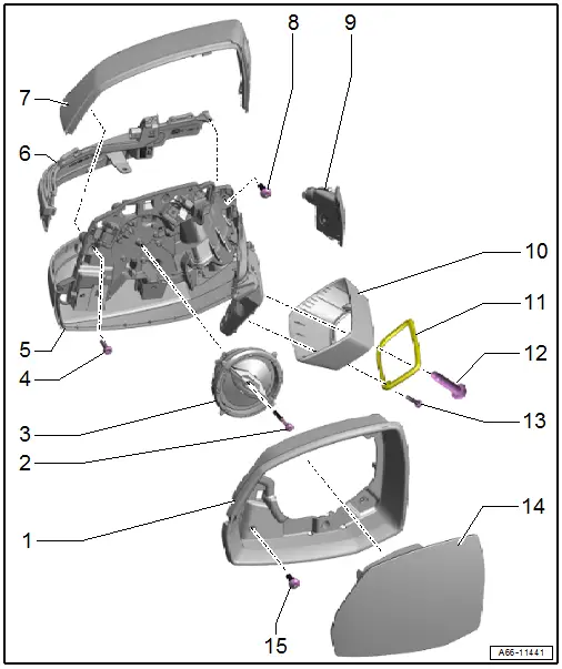
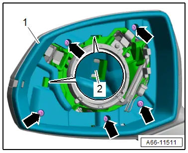
1 - Mirror Trim
- Removing and Installing. Refer to → Chapter "Mirror Trim, Removing and Installing".
2 - Bolt
- 1.5 Nm
3 - Mirror Adjusting Unit
- Removing and Installing. Refer to → Chapter "Mirror Adjusting Unit, Removing and Installing".
4 - Bolt
- 1.5 Nm
- Quantity: 2
5 - Exterior Rearview Mirror
- Removing and Installing. Refer to → Chapter "Exterior Rearview Mirror, Removing and Installing".
6 - Exterior Rearview Mirror Turn Signal Bulb
- Overview. Refer to → Electrical Equipment; Rep. Gr.94; Exterior Rearview Mirror Lamps; Overview - Exterior Rearview Mirror Lamps.
7 - Mirror Cap
- Removing and Installing. Refer to → Chapter "Mirror Cap, Removing and Installing".
8 - Bolt
- Tightening specification. Refer to → Electrical Equipment; Rep. Gr.94; Exterior Rearview Mirror Lamps; Overview - Exterior Rearview Mirror Lamps.
9 - Lane Change Assistance Warning Lamp in Exterior Rearview Mirror
- Overview. Refer to → Electrical Equipment; Rep. Gr.96; Lane Change Assistance; Overview - Lane Change Assistance.
10 - Mirror Base Cover
- Removing and Installing. Refer to → Chapter "Exterior Rearview Mirror, Removing and Installing".
11 - Seal
- For the mirror base
- Removing and Installing. Refer to → Chapter "Exterior Rearview Mirror, Removing and Installing".
12 - Bolt
- 12 Nm
13 - Bolt
- 1.5 Nm
- Quantity: 2
14 - Mirror Glass
- Removing and Installing. Refer to → Chapter "Mirror Glass, Removing and Installing".
15 - Bolt
- 1.5 Nm
- Quantity: 4
Exterior Rearview Mirror, Removing and Installing
Removing
- Remove the front door trim panel. Refer to → Body Interior; Rep. Gr.70; Front Door Trim Panels; Front Door Trim Panel, Removing and Installing.
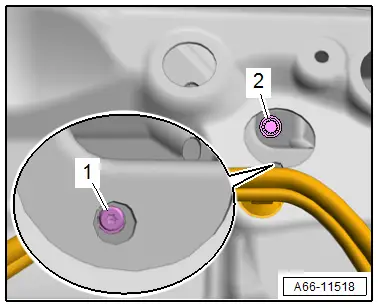
- Disconnect the connector -1- and if equipped, disconnect the connector -2-.
- Free up the wires.
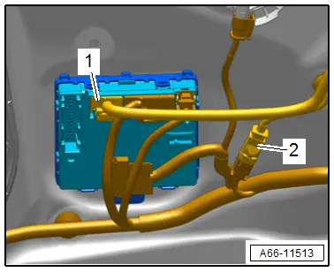
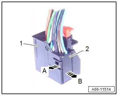
- Release the catch -arrow A- and remove the connector -2- from the connector housing -1--arrow B-.
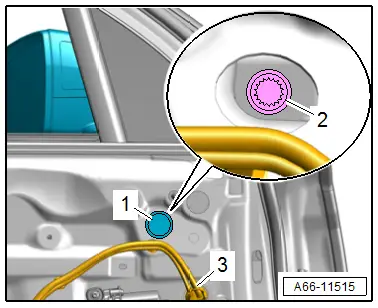
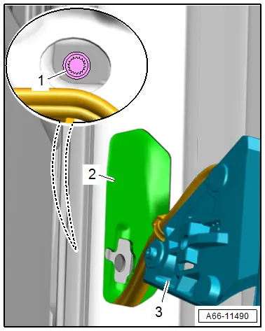
- Remove the plug -1- and push the grommet -3- through the door body toward the inside.
- Remove the bolt -2-.
- Remove the exterior rearview mirror upward and at the same time guide out the wiring harness with the grommet through the door body toward the rear.
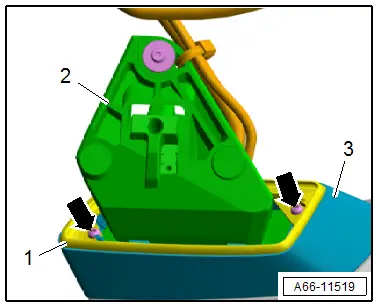
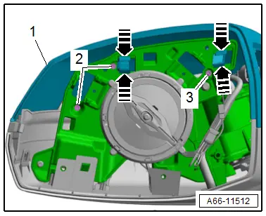
Removing the Seal and the Cover:
- Remove the bolts -arrows-.
- Unclip the seal -1- and remove it with the mirror base cover -3- from the exterior rearview mirror -2-.
Installing
Install in reverse order of removal and note the following:
- Guide the wiring harness through the door body.
- Engage the exterior rearview mirror -2- in the inner door mount -3- and tighten the bolt -1-.
- Check the gap dimension between the mirror base -1- and the outer door panel -2-.
- Dimension -x- top = dimension -x- bottom
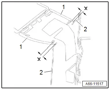
- To adjust the gap dimensions loosen the bolt -2- and turn the adjusting bolt -1- accordingly.
- Secure the adjusting screw again.
Tightening Specifications
- Refer to → Chapter "Overview - Exterior Rearview Mirror"
Mirror Glass, Removing and Installing
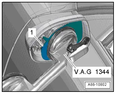
Special tools and workshop equipment required
- Double Suction Lifter -VAG1344-
- Safety Gloves
Removing
 WARNING
Risk of injury to the hands and eyes from glass fragments.
Getting cut is possible.
- Wear protective eyewear.
- Wear safety gloves.
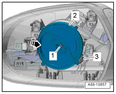
- Position the -VAG1344- in the center of the mirror glass -1-.
- Remove the mirror glass from the mirror adjusting unit using the - VAG1344-.
- Disconnect the connector -2- for the mirror heating on the back of the mirror glass -3-.
- If necessary unclip the connector -1- from the bracket and disconnect.
Installing
Install in reverse order of removal and note the following:
- Position the mirror glass on the mirror adjusting unit and press it on. While doing so, only press down on the center of the mirror.
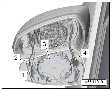
Mirror Adjusting Unit, Removing and Installing
Removing
- Remove the mirror glass. Refer to → Chapter "Mirror Glass, Removing and Installing".
- Remove the bolt -1-.
- Disengage the mirror adjusting unit -2- from the mount -arrow-.
- Disconnect the connector -3-.
- Remove the mirror adjusting unit.
Installing
Install in reverse order of removal.
Tightening Specifications
- Refer to → Chapter "Overview - Exterior Rearview Mirror"
Mirror Cap, Removing and Installing
Removing
- Equipped on some models: remove the lane change assistance warning lamp. Refer to → Electrical Equipment; Rep. Gr.96; Lane Change Assistance; Overview - Lane Change Assistance.
- Remove the mirror trim. Refer to → Chapter "Mirror Trim, Removing and Installing".
- Remove the bolts -2 and 3-.
- Release the catches -arrows- and remove the mirror cap -1- forward in the direction of travel.
Installing
Install in reverse order of removal.
Tightening Specifications
- Refer to → Chapter "Overview - Exterior Rearview Mirror"
Mirror Trim, Removing and Installing
Removing
- Remove the mirror glass. Refer to → Chapter "Mirror Glass, Removing and Installing".
- Remove the bolts -arrows-.
- Remove the mirror trim -1- in the direction of travel toward the rear to do so release the catches -2-.
- Guide the connectors out of the mount.
Installing
Install in reverse order of removal.
Tightening Specifications
- Refer to → Chapter "Overview - Exterior Rearview Mirror"

