Audi Q7: Driver Side Airbag
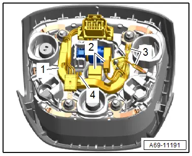
Overview - Driver Side Airbag
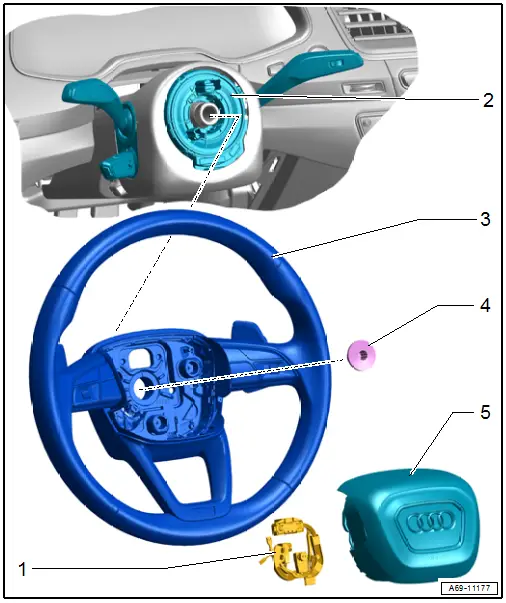
1 - Wiring Harness
- For Driver Airbag Igniter -N95- and Driver Airbag Release Valve Igniter -N490-
- Replacing. Refer to → Chapter "Airbag Connector, Replacing".
2 - Steering Column Electronics Control Module -J527-
- With Airbag Spiral Spring/Return Spring with Slip Ring -F138-
- Overview. Refer to → Electrical Equipment; Rep. Gr.94; Steering Column Switch Module; Overview - Steering Column Switch Module.
3 - Steering Wheel
- Overview. Refer to → Suspension, Wheels, Steering; Rep. Gr.48; Steering Wheel; Overview - Steering Wheel.
4 - Bolt
- Tightening specification. Refer to → Suspension, Wheels, Steering; Rep. Gr.48; Steering Wheel; Overview - Steering Wheel.
5 - Driver Side Airbag
- With the Driver Airbag Igniter -N95- and Driver Airbag Release Valve Igniter -N490-
 WARNING
Follow all safety precautions when working on pyrotechnic components. Refer to → Chapter "Safety Precautions for Pyrotechnic Components".
- Use a T10 TORX screwdriver, approximately 80 mm (3.14 in.) long
- Removing and installing. Refer to → Chapter "Airbag Unit with Igniter, Removing and Installing".
Airbag Unit with Igniter, Removing and Installing
Special tools and workshop equipment required
- T25 TORX-screwdriver, approximately 80 mm long, commercially available
Removing
 WARNING
- Follow all safety precautions when working on pyrotechnic components. Refer to → Chapter "Safety Precautions for Pyrotechnic Components".
- Follow all regulations when disposing of pyrotechnic components. Refer to → Chapter "Airbag, Belt Tensioner and Battery Cut-Out Units, Storing, Transporting and Disposing (Pyrotechnic Components)".
- Move the steering wheel as far to the rear and down as possible. Use the full steering column adjustment range for this.
- Disconnect the battery ground cable with the ignition turned on. Refer to → Electrical Equipment; Rep. Gr.27; Battery; Battery, Disconnecting and Connecting.
- Move the steering wheel out of the straight-ahead position by turning it clockwise 130º, so that the opening on the rear side of the steering wheel faces directly upward (approximately 12 o'clock position).
 Caution
There is a risk of damage the wires.
Do not use a flat-head screwdriver.
- Guide a Phillips head screwdriver or a T25 TORX screwdriver (approximately 80 mm long) all the way into the opening. A thin foam wall in the inside of the steering wheel must be punctured to do this.
- Release the locking bracket -1- for the driver side airbag -2- by pulling the screwdriver upward forcefully -arrow-.
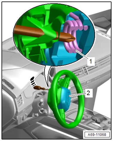
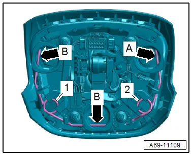
- The retainer -arrow A- is loosened from the steering wheel by pressing down the locking bracket -2- .
- Turn the steering wheel back 260º and repeat the procedure, while making sure that the airbag does not reengage on the loosened side.
- Loosen the remaining retainers -B arrows- from the steering wheel by pressing down the locking bracket -1-.
- Bring the steering wheel back into the center (wheels are straight).
 WARNING
Before handling pyrotechnic components (for example, disconnecting the connector), the person handling it must "discharge static electricity". For example, this can be done by briefly touching the door striker.
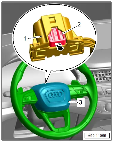
- Remove the driver side airbag -3- from the steering wheel slightly.
- Pull out the connector lock -2--arrow- and press it down, disconnect the connector -1-.
- Equipped on some models: disconnect the connector for the button in the steering wheel.
 WARNING
Set the airbag down so the impact cushion faces upward.
Installing
 WARNING
- Follow all safety precautions when working on pyrotechnic components. Refer to → Chapter "Safety Precautions for Pyrotechnic Components".
- Before handling pyrotechnic components (for example, connecting a connector), the person handling it must "discharge static electricity". For example, this can be done by briefly touching the door striker.
Install in reverse order of removal and note the following:
 Note
Note- Make sure the connectors are pushed in all the way and that they engage audibly.
- Make sure the wires are not pinched.
- Connect the spiral spring connector with the airbag connector coupling on the return spring with slip ring.
- Press in the connector to secure it in the pockets on the steering wheel.
- Position the driver side airbag in the steering wheel and press on until it audibly engages.
 WARNING
Repairing pyrotechnic components (for example the airbag and seat belt tensioner) incorrectly increases the risk of unintentional deployments when the battery is connected.
- The ignition must be on when connecting the battery.
- For personal safety when connecting the battery, stay out of the deployment area of the airbag and maintain a distance from the seat belt tensioners/seat belts.
- Make sure that there are no other people inside the vehicle at the time when the battery is connected.
- Connect the battery ground cable with the ignition switched on. Refer to → Electrical Equipment; Rep. Gr.27; Battery; Battery, Disconnecting and Connecting.
- Check and erase the airbag control module DTC memory because faults can be stored from when the connectors are disconnected. Use the Vehicle Diagnostic Tester → Vehicle diagnostic tester.
Installation instructions: for example tightening specifications, replacing components. Refer to → Chapter "Overview - Driver Side Airbag".
Airbag Connector, Replacing
Removing
 WARNING
Follow all safety precautions when working on pyrotechnic components. Refer to → Chapter "Safety Precautions for Pyrotechnic Components".
- Remove the driver side airbag. Refer to → Chapter "Airbag Unit with Igniter, Removing and Installing".
 WARNING
Before handling pyrotechnic components (for example, disconnecting the connector), the person handling it must "discharge static electricity". This can be done by briefly touching the door striker pin, for example.
- Release the connector lock -2- for the connector -1- with a small screwdriver in direction of -arrow-.
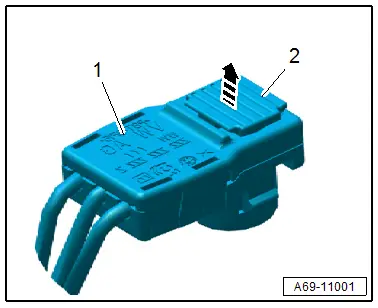
- Disconnect the connectors -2- from the Driver Airbag Igniter -N95- and Driver Airbag Release Valve Igniter -N490-.
- Disconnect the connectors -3 and 4- by releasing the retaining tab.
- Disengage and remove the wiring harness -1- at the brackets.
Installing
 WARNING
- Follow all safety precautions when working on pyrotechnic components. Refer to → Chapter "Safety Precautions for Pyrotechnic Components".
- Before handling pyrotechnic components (for example, connecting the connector), the person handling it must "discharge static electricity". This can be done by briefly touching the door striker pin, for example.
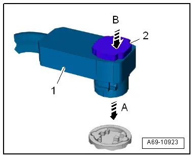
- Connect the connector -1- to the airbag igniter in direction of -arrow A-.
- Press in the connector lock -2- in direction of -arrow B-. While doing this, the connector is pushed into the airbag igniter all the way and locks into place.
Installation is performed in reverse order of removal, while noting the following:
 Note
Note
Make sure the connectors are pushed in all the way and that they engage audibly.
Installation notes, for example tightening specifications, replacing components. Refer to → Chapter "Overview - Driver Side Airbag".

