Audi Q7: General Information for Actuators
 Note
Note
- Depending on vehicle equipment, there are different versions of the A/C system for the Audi Q7. Make sure to use the correct version and pay attention to the allocation of different components. Refer to → Chapter "A/C System Versions" and Parts Catalog.
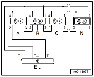
- For this vehicle, there are various actuators (-A- through -N-) on the front heater and A/C unit, under the instrument panel, on the rear heater and A/C unit or on the rear air distribution housing that are adapted and activated via data wires. The various actuators (-A- through -N-) are connected to the Front A/C Display Control Head -E87- / to the Rear A/C Display Control Head -E265- in a row via these data wires (LIN bus 1, LIN bus 2). If there is a malfunction in an actuator that is connected via this data wire or if it is in the wiring, this malfunction can result in various DTC memory entries with different malfunction types. Refer to Vehicle Diagnostic Tester in the "Guided Fault Finding" function and refer to → Wiring diagrams, Troubleshooting & Component locations.
- Depending on the vehicle equipment, many different actuators are connected to the Front A/C Display Control Head -E87- or the Rear A/C Display Control Head -E265- via the data wire (LIN bus 2). If there is a malfunction in an actuator that is connected via this data wire or if it is in the wiring, this malfunction can result in various DTC memory entries with different malfunction types. Refer to Vehicle Diagnostic Tester in the "Guided Fault Finding" function and refer to → Wiring diagrams, Troubleshooting & Component locations.
- There are currently seven actuators for the "Low" or "Mid" A/C system and 15 actuators for the "Mix" or "High" A/C system that are connected in series to the Front A/C Display Control Head -E87- via the data wire (LIN bus 1). Refer to → Wiring diagrams, Troubleshooting & Component locations.
- For vehicles with a "Mid" or "Mix" A/C system, there are currently four additional actuators (installed on the air distribution housing under the center console) that are connected in series to the Front A/C Display Control Head -E87- via the data wire (LIN bus 2). Refer to → Wiring diagrams, Troubleshooting & Component locations.
- For vehicles with a "High" A/C system, there are currently seven additional actuators (installed on the rear heater and A/C unit under the center console) that are connected in series to the Rear A/C Display Control Head -E265- via the data wire (LIN bus 1). Refer to → Wiring diagrams, Troubleshooting & Component locations.
- For vehicles with a "High" A/C system, the actuators installed on the rear heater and A/C unit (current quantity: 7) are connected to the Rear A/C Display Control Head -E265- via a data wire. These adjustment motors are activated in the same way as the adjustment motors connected to the Front A/C Display Control Head -E87- (also via this series connection). Refer to → Wiring diagrams, Troubleshooting & Component locations.
- The actuator sequence in the wiring is currently dependent on the A/C system version (refer to → Chapter "A/C System Versions") and on the vehicle version (refer to → Wiring diagrams, Troubleshooting & Component locations).
- In the "basic setting" function, only adapt the actuators connected to the different data wires (LIN bus 1 and LIN bus 2 to the Front A/C Display Control Head -E87- and LIN bus 1 to the Rear A/C Display Control Head -E265-) if there are no malfunctions stored in the Front A/C Display Control Head -E87- (or in Rear A/C Display Control Head -E265-) which have a cause other than an actuator that is not adapted or is incorrectly adapted. In addition, adapt the actuators one after the other via the two data wires on the Front A/C Display Control Head -E87-. If adapting the actuators connected to both data wires is desired, check the DTC memory of the Front A/C Display Control Head -E87- (and / or the Rear A/C Display Control Head -E265-) after an adaptation was performed via a data wire. Only conduct the adaptation operation via the second data line if the first operation was completed successfully. If there is a malfunction in one of the two data wires for the Front A/C Display Control Head -E87-, it may no longer be possible, depending on the malfunction, to determine in which of the data wires the malfunction occurred, if the adaptation procedure was performed immediately one after the other via both data wires for the Front A/C Display Control Head -E87-. Refer to Vehicle Diagnostic Tester in the "Guided Fault Finding" function.
Depending on the operating condition or the A/C system Guided Fault Finding function where a certain malfunction appears, the effect of the malfunction and the type of malfunction stored in the DTC memory is different. Refer to Vehicle Diagnostic Tester in the "Guided Fault Finding" function.
- If there is a malfunction in the actuator sequence (two or more connectors on the actuators or the actuators were interchanged during installation)
- The function of the adjustment motors with interchanged connectors may be OK until the next basic setting (addressing of the adjustment motors). However, in the next basic setting, these adjustment motors will be incorrectly adapted (addressed) and the activation of the adjustment motors (and therefore the doors) will now be incorrect (incorrect allocation).
- If the connectors at the adjustment motors are interchanged, these adjustment motors are incorrectly adapted in the basic setting (addressed) and the activation of the adjustment motors (and thus the doors) is incorrect (incorrect allocation). In the event interchanged connectors are suspected, check the wire connections between the adjustment motors. Refer to → Wiring diagrams, Troubleshooting & Component locations.
- Depending on the adjustment range for this actuator, an incorrect end stop is recognized during the basic setting and this is stored as a malfunction in the event memory, and the basic setting is terminated.
- If the wrong door moves, then the air flow direction is incorrect. This is not always recognized as a fault depending on the adjustment range of the actuator. Therefore, always label all connectors and adjustment motors with the installation location before disconnecting them, and perform a basic setting after reconnecting them.
- If there is a malfunction in normal A/C system operation, then the following DTC memory entries can result, depending on the type of malfunction.
- If there is a malfunction in the positive or ground connection to an actuator, this actuator can no longer exchange information with the Front A/C Display Control Head -E87- (or the Rear A/C Display Control Head -E265-) and this actuator is stored in the DTC memory.

- If there is a malfunction in the data wire to an actuator (for example, a short circuit in the connector to contact "2" of the actuator -B-), then this actuator and all actuators connected in series after this actuator (-C through N-) can no longer exchange information with the Front A/C Display Control Head -E87- (or the Rear A/C Display Control Head -E265-) and this actuator as well as all the other connected actuators are stored in the DTC memory.
- If a malfunction occurs in the actuator electronics (for example, in actuator -B-), the actuator -B- may still be able to exchange information with the Front A/C Display Control Head -E87- (or the Rear A/C Display Control Head -E265-) depending on the type of malfunction, however all the actuators connected after this one (-C through N-) will be stored in the DTC memory.
- If there is a malfunction during the basic setting of the A/C system, then the following malfunction entries can result, depending on the type of malfunction.
- If there is a malfunction in the positive or ground connection to an actuator (for example, to actuator -B-), then this actuator cannot exchange information with the Front A/C Display Control Head -E87- (or the Rear A/C Display Control Head -E265-) and it will not be recognized during the basic setting. During the basic setting, all the actuators from the last actuator beginning with -N- are re-allocated and re-assigned; this actuator is no longer in sequence. The Front A/C Display Control Head -E87- (or the Rear A/C Display Control Head -E265-) detects that an actuator is missing and stores the first actuator in the series connection as missing. In addition, the malfunction "automatic addressing malfunctioning" is displayed and "upper or lower limit value exceeded" may additionally be displayed for certain adjustment motors.
- If there is a malfunction in the data wire to an actuator (for example, a short circuit in the connector to contact "2" of actuator -C-), this actuator and all actuators connected in the series after this one can no longer exchange information with the Front A/C Display Control Head -E87- (or the Rear A/C Display Control Head -E265-), and these actuators are not recognized during the basic setting. During the basic setting, all the actuators from the last actuator beginning with -N- are re-allocated and re-assigned; these actuators are no longer in sequence. The Front A/C Display Control Head -E87- (or Rear A/C Display Control Head -E265-) detects that several actuators are missing (for example, only the actuators -B--A- are detected as incorrectly assigned and adapted). All other adjustment motors are stored as missing in the event memory and the malfunction "automatic addressing malfunctioning" is displayed.
- If there is a malfunction in the actuator electronics or one occurs during the basic setting (for example, in actuator -C-), this actuator may still be able to exchange information with the Front A/C Display Control Head -E87- (or the Rear A/C Display Control Head -E265-), depending on the type of malfunction. However, data can no longer be exchanged with all the actuators connected after this one (up to actuator -N-). The Front A/C Display Control Head -E87- (or Rear A/C Display Control Head -E265-) detects that several actuators are missing (the actuators -C through A- may only be incorrectly assigned and adapted). All other adjustment motors are stored as missing in the event memory and the malfunction "automatic addressing malfunctioning" is displayed.