Audi Q7: Instrument Panel Central Tube
Overview - Instrument Panel Central Tube
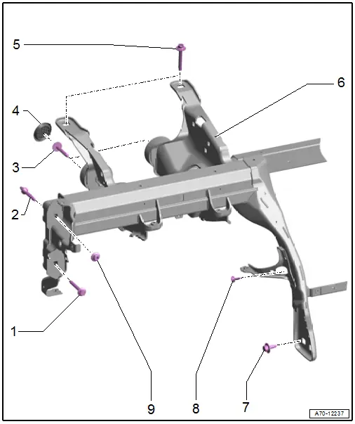
1 - Bolt
- 20 Nm
- Quantity: 1 on the left and right side
 Caution
There is a risk of malfunctions do to a faulty ground connection.
The counter threaded and contact surface must be free of paint, coating, and corrosion, the threaded connection serves as the ground connection.
2 - Threaded Pin
- 20 Nm
 Caution
There is a risk of malfunctions do to a faulty ground connection.
The counter threaded and contact surface must be free of paint, coating, and corrosion, the threaded connection serves as the ground connection.
3 - Bolt
- 20 Nm
- Quantity: 2
4 - Plug
- Quantity: 2
5 - Bolt
- 20 Nm
- Quantity: 3
6 - Central Tube
- For the instrument panel
- Removing and installing. Refer to → Chapter "Instrument Panel Central Tube, Removing and Installing".
7 - Bolt
- 20 Nm
- Left: 2; Right: 1
8 - Bolt
- 3.6 Nm
- For A/C unit
- Quantity: 5
9 - Nut
- 20 Nm
- Quantity: 1 on the left and right side
- Replace after removing
 Caution
There is a risk of malfunctions do to a faulty ground connection.
The contact surface must be free of paint, coating, and corrosion, the threaded connection serves as the ground connection.
Instrument Panel Central Tube, Removing and Installing
Removing
- Remove the windshield wiper motor. Refer to → Electrical Equipment; Rep. Gr.92; Windshield Wiper System; Windshield Wiper Motor V, Removing and Installing.
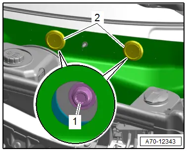
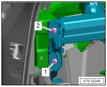
- Remove the plugs -2- and remove the bolt -1- for the central tube on the plenum chamber bulkhead.
- Remove the instrument panel. Refer to → Chapter "Instrument Panel, Removing and Installing".
- Remove the windshield. Refer to → Body Exterior; Rep. Gr.64; Windshield; Windshield, Removing and Installing.
- Remove the air duct to the driver side instrument panel vent. Refer to → Heating, Ventilation and Air Conditioning; Rep. Gr.87; Air Duct; Overview - Air Routing and Air Distribution in Vehicle Interior.
- Remove the air duct center piece to the center defroster vent. Refer to → Heating, Ventilation and Air Conditioning; Rep. Gr.87; Air Duct; Overview - Air Routing and Air Distribution in Vehicle Interior.
- Remove the left A-pillar fuse panel from the instrument panel central tube. Refer to → Electrical Equipment; Rep. Gr.97; Relay Panels, Fuse Panels and E-Boxes; Component Location Overview - Relay Panels, Fuse Panels and E-Boxes.
- Equipped on some models: remove the ionizer with the left bracket from the instrument panel central tube. Refer to → Heating, Ventilation and Air Conditioning; Rep. Gr.87; Additional Components for Control and Regulation.
- Disconnect the cable tie, unclip the wires on the instrument panel central tube and free them up.
- Unbolt the steering column from the instrument panel central tube and lay it on the floor of the vehicle. Refer to → Suspension, Wheels Steering; Rep. Gr.48; Steering Column; Steering Column, Removing and Installing.
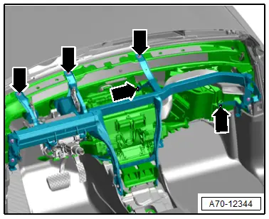
- Remove the bolts -arrows-.
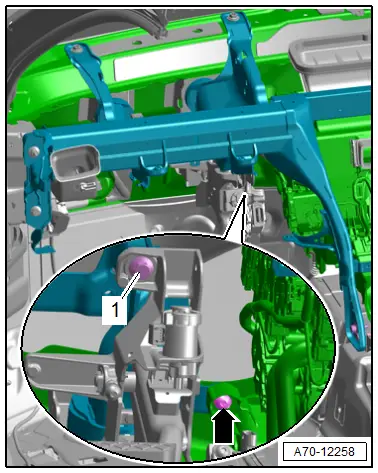
- Remove the bolt -1-.
- Remove the bolt -arrow- for the A/C unit.
 Note
Note
For reinstallation, mark the vertical and lengthwise position on the instrument panel central tube.
- Push aside the carpet in the area near the threaded connection and remove the bolts -1-.
- Remove the bolt -2- for the A/C unit.
- Repeat the process on the opposite side.
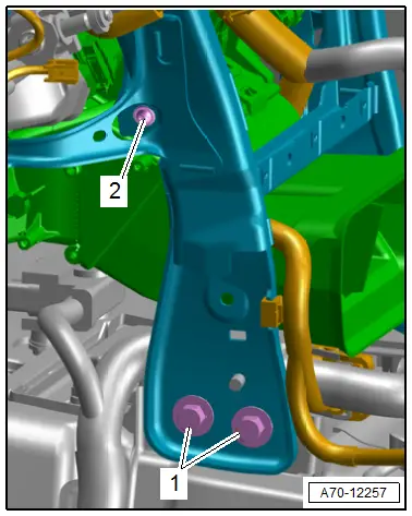
- Remove the bolt -1- and nut -2- for the instrument panel central tube
- Repeat the process on the opposite side.
- Unclip the wire for the instrument panel central tube disengage and free up.
 Note
Note
Two technicians are needed to remove instrument panel central tube.
- Disengage the instrument panel central tube from the A/C unit and remove from the vehicle interior toward the rear.
Installing
- Carefully insert the instrument panel central tube in the body.
- Align the instrument panel central tube according to the marks applied to the A-pillar during removal.
- Tighten the nuts and bolts for the instrument panel central tube near the A-pillar on both the driver and front passenger sides.
Installation is performed in reverse order of removal, while noting the following:
- Install the steering column. Refer to → Suspension, Wheels, Steering; Rep. Gr.48; Steering Column; Overview - Steering Column.
- Mounting bracket for pedal assembly. Refer to → Brake System; Rep. Gr.46; Brake Pedal; Overview - Brake Pedal.
Check the Installation Location of the Instrument Panel Central Tube
- Insert the instrument panel to test.
- Secure the instrument panel at left and right to the instrument panel central tube.
- Close the doors.
- Check whether the gap dimension between instrument panel and left and right doors are even.
- Check whether the height of instrument panel aligns with molding in door trim.
- If the adjustment is incorrect, note lateral and/or vertical deviation.
- Loosen the instrument panel central tube threaded connections.
- Adjust the instrument panel central tube according to the noted deviations.
- Tighten the bolt -1- and nut -2- for the instrument panel central tube at the A-pillar on both the driver and front passenger sides.
 WARNING
The ignition must be on when connecting the battery. If pyrotechnic components (for example, airbag, belt tensioner) are not repaired correctly, they may deploy unintentionally after connecting battery. There must not be anyone in the vehicle interior when connecting the battery.
- Install the windshield. Refer to → Body Exterior; Rep. Gr.64; Windshield; Windshield, Removing and Installing.
- Connect the battery ground cable with the ignition turned on. Refer to → Electrical Equipment; Rep. Gr.27; Battery; Battery, Disconnecting and Connecting.
 Note
Note
If the Airbag Indicator Lamp -K75- indicates a fault, check the Diagnostic Trouble Code (DTC) memory, erase it and check it again using the Vehicle Diagnostic Tester.
Installation notes, for example tightening specifications, replacing components. Refer to → Chapter "Overview - Instrument Panel Central Tube".


