Audi Q7: Instrument Panel Vent, Removing and Installing
Driver Side Instrument Panel Vent, Removing and Installing
Special tools and workshop equipment required
- Trim Removal Wedge -3409-
Removing
- Move the steering wheel as far up and backward as possible to be able to use the full steering column adjustment range.
- Remove the driver side instrument panel side cover. Refer to → Chapter "Instrument Panel Side Cover, Removing and Installing".
- Remove the light switch trim. Refer to → Chapter "Light Switch Trim, Removing and Installing".
- Removing the decorative trim for the driver side instrument panel. Refer to → Chapter "Instrument Panel Decorative Trim, Removing and Installing, Driver Side".
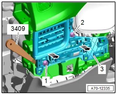
- Remove the bolts -1 and 2-.
- Unclip the instrument panel vent -3- using the -3409--arrows-.
- Disengage the remaining retainers, carefully remove the instrument panel vent and disconnect the connectors.
Installing
Install in reverse order of removal.
Installation notes, for example tightening specifications, replacing components. Refer to → Chapter "Overview - Instrument Panel".
Passenger Side Instrument Panel Vent, Removing and Installing
Special tools and workshop equipment required
- Trim Removal Wedge -3409-
Removing
- Remove the front passenger side instrument panel side cover. Refer to → Chapter "Instrument Panel Side Cover, Removing and Installing".
- Remove A/C display control head trim. Refer to → Chapter "Display Control Head Trim, Removing and Installing".
- Remove the instrument panel decorative trim on the front passenger side. Refer to → Chapter "Instrument Panel Decorative Trim, Removing and Installing, Front Passenger Side".
- Remove the instrument panel decorative trim in the center. Refer to → Chapter "Instrument Panel Decorative Trim, Removing and Installing, Center".
- Remove the access/start authorization switch trim. Refer to → Chapter "Access/Start Authorization Switch Trim, Removing and Installing".
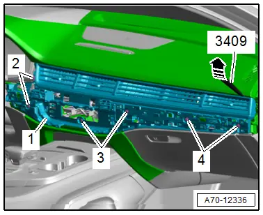
- Remove the bolts -2, 3 and 4-.
- Unclip the instrument panel vent -1- using the -3409- in direction of -arrow-.
- Disengage the remaining retainers, carefully remove the instrument panel vent and disconnect the connectors.
Installing
Install in reverse order of removal.
Installation notes, for example tightening specifications, replacing components. Refer to → Chapter "Overview - Instrument Panel".
Front Center Defroster Vent, Removing and Installing
Special tools and workshop equipment required
- Trim Removal Wedge -3409-
Removing
- Remove the sunlight photo sensor. Refer to → Heating, Ventilation, and Air Conditioning; Rep. Gr.87; Additional Components for Control and Regulation; Sunlight Photo SensorG107, Removing and Installing.
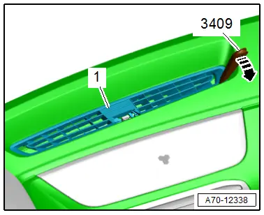
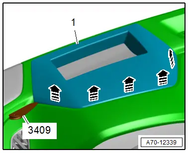
- Unclip the defroster vent -1- using the -3409--arrow-.
- Disengage the remaining retainers and remove the defroster vent.
Installing
Install in reverse order of removal.
Installation notes, for example tightening specifications, replacing components. Refer to → Chapter "Overview - Instrument Panel".
Side Defroster Vent, Removing and Installing
Special tools and workshop equipment required
- Trim Removal Wedge -3409-
Removing
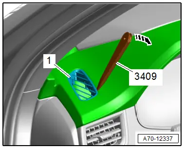
- Unclip the defroster vent -1- using the -3409- in direction of -arrow-.
- Disengage the remaining retainers and remove the defroster vent.
Installing
Install in reverse order of removal.
Installation notes, for example tightening specifications, replacing components. Refer to → Chapter "Overview - Instrument Panel".
Windshield Projection (Head-Up Display) Trim, Removing and Installing
Special tools and workshop equipment required
- Trim Removal Wedge -3409-
Removing
- Unclip the windshield projection trim -1- using the -3409- in direction of -arrows-.
- Remove the windshield projection trim toward the rear.
Installing
Install in reverse order of removal.
Installation notes, for example tightening specifications, replacing components. Refer to → Chapter "Overview - Instrument Panel".

