
Audi Q7: Latch, Removing and Installing
Removing
- Remove the headlamps. Refer to → Electrical Equipment; Rep. Gr.94; Headlamps; Headlamps, Removing and Installing.
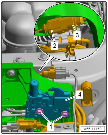
- Disconnect the connector -2-.
- Free up the connector -3-.
- Remove the bolts -1-.
- Remove the latch -4- until both the cables are visible.
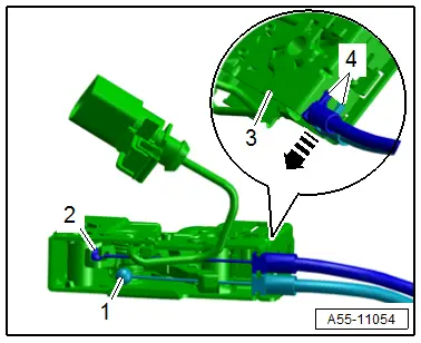
- Release the catches -4- and remove the cable bracket from the mount -3--arrow-.
- Remove the cable nipples -1 and 2- from the release lever on the latch.
- Remove the latch.
Installing
Install in reverse order of removal.
Tightening Specifications
- Refer to → Chapter "Overview - Release on Latch"
Latch Release Lever, Removing and Installing
Removing
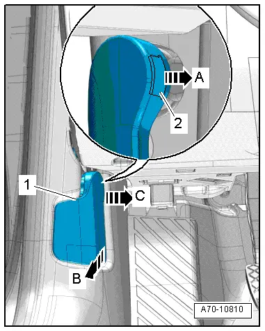
- Pull the clip -2- out of the release lever -1- slightly -arrow A- using a small screwdriver.
- Pull the operating lever back -arrow B- to release the hood and hold it in this position.
- At the same time, pull the release lever so it is level with the center of the vehicle and out of its mount -arrow C-.
Installing
Install in reverse order of removal and note the following:
- Slide the clip all the way into the release lever.
- Press the release lever onto the mount in the mounting bracket and engage it.
Hook Release Lever, Removing and Installing
Removing
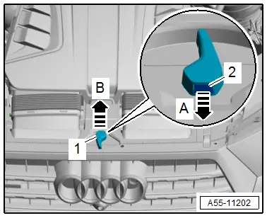
- Pull the clip -2- out of the release lever -1- slightly -arrow A- using a small screwdriver.
- Remove the release lever upward -arrow B-.
Installing
Install in reverse order of removal and note the following:
- Slide the clip all the way into the release lever.
- Press the release lever on until it audibly engages.
Latch Release Lever Mounting Bracket, Removing and Installing
Removing
- Remove the latch release lever. Refer to → Chapter "Latch Release Lever, Removing and Installing".
- Remove the A-pillar lower trim panel. Refer to → Body Interior; Rep. Gr.70; Vehicle Interior Trim Panels; A-Pillar Trim Panel, Removing and Installing.
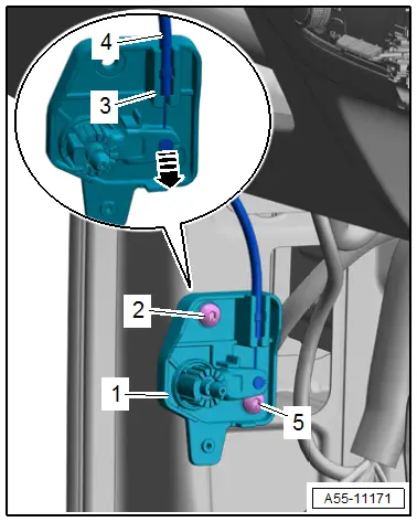
- Remove the bolts -2 and 5-.
- Remove the mounting bracket -1-.
- Loosen the release cable -4- from the support bracket -3- and disengage the release cable nipple -arrow-.
Installing
Install in reverse order of removal.
Tightening Specifications
- Refer to → Chapter "Overview - Release in Vehicle Interior"
Mounting Bracket with Hook Release Lever Release Cable, Removing and Installing
Removing
- Remove the hook release lever. Refer to → Chapter "Hook Release Lever, Removing and Installing".
- Remove the lock carrier cover. Refer to → Chapter "Lock Carrier Cover, Removing and Installing".
- Remove the latch and disengage the mounting bracket release cable. Refer to → Chapter "Latch, Removing and Installing".
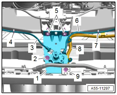
- Free up the wiring harness -8-.
- Pry out the clips -4 and 7-.
- Remove the bolts -5 and 9-.
- Versions with radiator shutter: remove the bolt -2-.
- Remove the mounting bracket -1- and free up the release cables -3 and 6-.
Installing
Install in reverse order of removal.
Tightening Specifications
- Refer to → Chapter "Overview - Release on Latch"

