Audi Q7: Rear Center Console Vent, Removing and Installing
Special tools and workshop equipment required
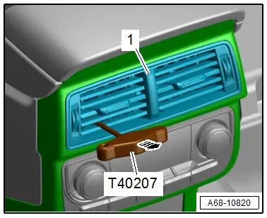
- Hook Tool -T40207-
Removing
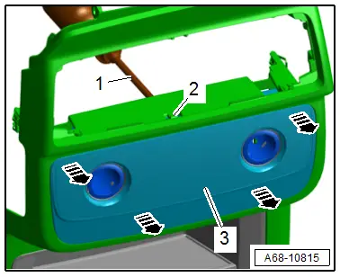
- Carefully guide the -T40207- between the slats and hook it to the rear of the vent -1-.
- Alternating between the sides, carefully remove the vent from the installation opening in direction of -arrow-.
- Disconnect the connector.
Installing
Install in reverse order of removal.
Installation notes, for example tightening specifications, replacing components. Refer to → Chapter "Overview - Center Console, Rear Trim".
Center Console Bracket, Removing and Installing
Removing
- Remove the center console support. Refer to → Chapter "Center Console Support, Removing and Installing".
- Remove the rear heater and A/C unit. Refer to → Heating, Ventilation and Air Conditioning; Rep. Gr.87; Rear Heater and A/C Unit; Heater and A/C Unit, Removing and Installing.
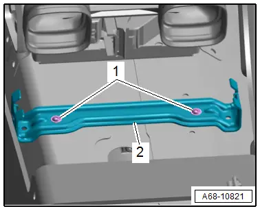
- Unclip and free up the wires on the bracket.
- Remove the bolts -1-.
- Remove the center console bracket -2-.
Installing
Install in reverse order of removal.
Installation notes, for example tightening specifications, replacing components. Refer to → Chapter "Overview - Center Console, Support/Cover".
Display Control Head Trim, Removing and Installing
Center Console Insert Trim, Removing and Installing
Removing
- Remove the center console insert. Refer to → Chapter "Center Console Insert, Removing and Installing".
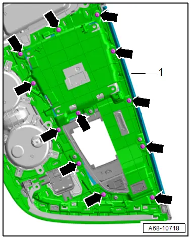
- Place the center console insert on a soft surface.
- Remove the bolts -arrows-.
- Remove the decorative trim -1-.
Installing
Install in reverse order of removal.
Installation notes, for example tightening specifications, replacing components. Refer to → Chapter "Overview - Center Console, Insert".
A/C System Display Control Head Trim, Removing and Installing
Removing
- Remove the center console rear trim. Refer to → Chapter "Center Console Rear Trim, Removing and Installing".
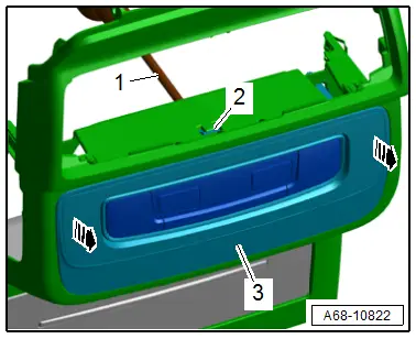
- Release the tab -2- using a screwdriver -1- and remove the trim at the same time.
- Release the rest of the tabs and remove the display control head trim -3- in direction of -arrows-.
Installing
Install in reverse order of removal.
Installation notes, for example tightening specifications, replacing components. Refer to → Chapter "Overview - Center Console, Insert".
Rear Seat Heating Button/Socket Trim, Removing and Installing
Removing
- Remove the center console rear trim. Refer to → Chapter "Center Console Rear Trim, Removing and Installing".
- Release the tab -2- using a screwdriver -1- and remove the trim at the same time.
- Release the rest of the tabs and remove the socket/button trim -3- in direction of -arrows-.
Installing
Install in reverse order of removal.
Installation notes, for example tightening specifications, replacing components. Refer to → Chapter "Overview - Center Console, Rear Trim".

