Audi Q7: Spoiler
Overview - Spoiler
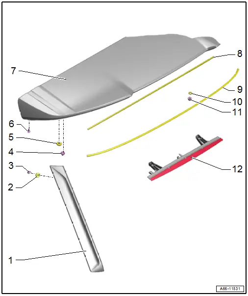
1 - Side Spoiler
- Removing and Installing. Refer to → Chapter "Side Spoiler, Removing and Installing".
2 - Foam Seal
- Replace if damaged
3 - Clip
- Quantity: 2
4 - Clip
- Quantity: 5
5 - Foam Seal
- For the securing pin
- Replace if damaged
- Quantity: 3
6 - Bolt
- 2.5 Nm
7 - Spoiler
- Removing and Installing. Refer to → Chapter "Spoiler, Removing and Installing".
8 - Rear Foam Seal
- Replace if damaged
9 - Front Foam Seal
- Replace if damaged
10 - Foam Seal
- Replace if damaged
11 - Nut
- 4 Nm
- Quantity: 4
12 - High-Mounted Brake Lamp
- Overview. Refer to → Electrical Equipment; Rep. Gr.94; High-Mounted Brake Lamp; Overview - High-Mounted Brake Lamp.
Spoiler, Removing and Installing
Special tools and workshop equipment required
- Wedge Set -T10383-
Removing
- Remove the rear lid upper trim panel. Refer to → Body Interior; Rep. Gr.70; Luggage Compartment Trim Panels; Rear Lid Upper Trim Panel, Removing and Installing
- Disconnect the connectors -1 and 3-.
- Free up the cable grommets -2- by releasing the retainers -arrows-.
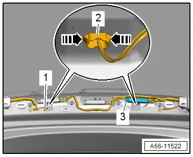
- Remove the nuts -2 and 3- and the bolt -1-.
- Close the rear lid.
- Remove the spoiler -4- with the -T10383/1- from the rear lid.
- If the spoiler is to be replaced, also remove the following components:
- High-mounted brake lamp. Refer to → Electrical Equipment; Rep. Gr.94; High-Mounted Brake Lamp; High-Mounted Brake Lamp Bulb Removing and Installing.
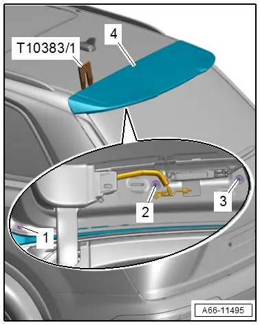
Installing
Install in reverse order of removal and note the following:
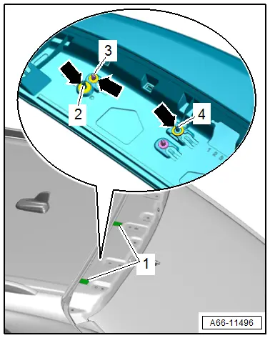
- Check the anti-friction film -1- and foam seals -arrows- for damage,
- The foam seals must be resting on the clips -3-, the securing tabs -2- and the threaded pins -4-.
Tightening Specifications
- Refer to → Chapter "Overview - Spoiler"
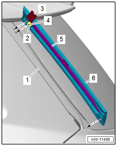
Side Spoiler, Removing and Installing
Special tools and workshop equipment required
- Roller -3356-
- Wiring Harness Repair Set - Hot Air Blower -VAS1978/14A-
- Wedge Set -T10383-
- Cleaning Solution -D 009 401 04-
Removing
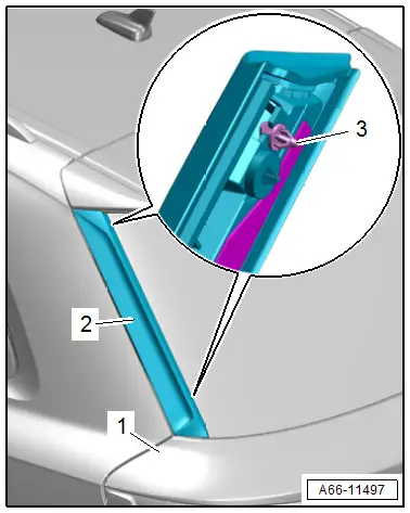
- Carefully warm the spoiler -2- using the -VAS1978/14A-.
- Carefully pry up the spoiler in the area of the clips -3- using a -T10383/1- from the rear lid -1-.
- Remove the spoiler.
Installing
Install in reverse order of removal and note the following:
- Check the foam seal -4- for damage.
- Clean the adhesive surface using the Cleaning Solution -D 009 401 04-.
- Fold back the ends of the protective film, or attach a pulling aid to the protective film -3-.
- Align the spoiler -6- with an alignment pin -2- on the rear lid -1-.
- Remove the protective film from the pulling aids and from the adhesive tape -5-.
- Push on the spoiler until it engages audibly on the rear lid.
- Push the entire length of the spoiler on using the -3356-.
- Vehicle resting time is at least one hour at room temperature.
- It is durable after at least 24 hours.