Audi Q7: Supercharger, Securing on Engine and Transmission Holder
Supercharger, Securing to Engine/Transmission Holder for Repair Work
![]() Note
Note
The openings on the bottom of the supercharger housing should make it possible to see and reach the charge air cooler.
Special tools and workshop equipment required
- Engine and Gearbox Bracket -VAS6095A-
- Gearbox Support -T40206- with -T40206/1-
- Support -T40304-
Procedure
- Supercharger removed. Refer to → Chapter "Supercharger, Removing and Installing".
- Insert the Gearbox Support -T40206- with -T40206/1- in the Engine and Gearbox Bracket -VAS6095A-.
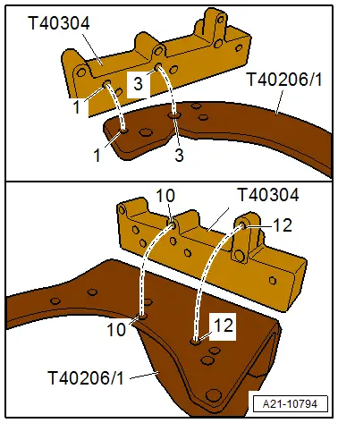
- Install the Supercharger Module Support -T40304- next loosely on the -T40206/1- while doing so pay attention to the allocation of the holes -1, 3, 10 and 12- on the mount and the Gearbox Support -T40206-.
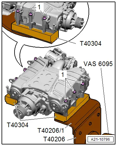
- Place the supercharger on the Support -T40304- as shown in the illustration.
- It is possible to see and reach the charge air cooler through the openings on the bottom inside the supercharger housing.
- Tighten the bolts -1- evenly on the left and the right diagonally hand-tight.
- Tighten the Support -T40304- to 21 Nm on the -T40206/1-.
- Tighten the left and right bolts -1- diagonally to 21 Nm.

Supercharger, Securing to Engine/Transmission Holder for Leak Test
![]() Note
Note
The seals on the Supercharger Module Support -T40304- should seal off the openings inside the compressor housing during the leakage test.
Special tools and workshop equipment required
- Engine and Gearbox Bracket -VAS6095A-
- Gearbox Support -T40206- with -T40206/1-
- Support -T40304-
Procedure
- Supercharger removed. Refer to → Chapter "Supercharger, Removing and Installing".
- Insert the Gearbox Support -T40206- with -T40206/1- in the Engine and Gearbox Bracket -VAS6095A-.
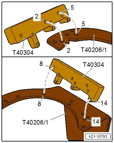
- Install the Support -T40304- next loosely on the -T40206/1- while doing so pay attention to the allocation of the holes -2, 5, 8 and 14- on the mount and the Gearbox Support -T40206-.
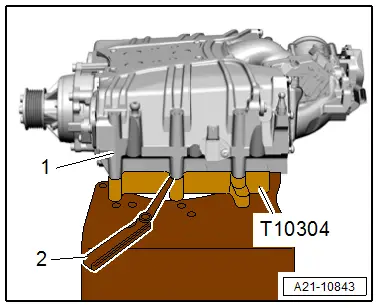
- Place the supercharger on the Support -T40304- as shown in the illustration.
- The seals on the supports seal off the openings in the supercharger housing.
- Lightly tighten the bolts -1- evenly on the left and the right diagonally hand-tight.
- Tighten the Support -T40304- to 21 Nm on the -T40206/1-.
- Check that the bolts are tightened evenly with the feeler gauge -2- and adjust if required.
- A uniform gap must be all around between the supercharger -1- and the Support -T40304-.
- Maximum gap dimension tolerance = 0.2 mm
Turbocharger Speed Sensor 1 -G688-, Removing and Installing
Removing
![]() Caution
Caution
This procedure contains mandatory replaceable parts. Refer to component overview prior to starting procedure.
Mandatory Replacement Parts
- O-ring - Turbocharger speed sensor 1
- Remove the engine cover. Refer to → Chapter "Engine Cover, Removing and Installing".
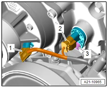
- Disconnect the connector -2-.
- Remove the bolt -3- and the Turbocharger Speed Sensor 1 -G688-.
![]() Note
Note
Ignore -1-.
Installing
Install in reverse order of removal and note the following:
![]() Note
Note
Replace the seal.
- Install the engine cover. Refer to → Chapter "Engine Cover, Removing and Installing".
Tightening Specifications
- Refer to → Chapter "Overview - Supercharger"

