Audi Q7: Airbag Control Module
Overview - Airbag Control Module
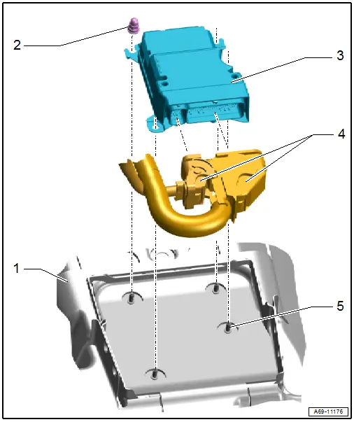
1 - Center Tunnel
2 - Nut
- 9 Nm
- Quantity: 4
- The thread must be paint and contaminant free, nut and ground pins serve as ground connection for the control module.
3 - Airbag Control Module -J234-
- Removing and installing. Refer to → Chapter "Airbag Control Module -J234-, Removing and Installing".
- The control module is grounded via the housing with the body.
4 - Connectors
5 - Threaded Pins
- Quantity: 4
- The thread must be paint and contaminant free, nut and ground pins serve as ground connection for the control module.
Airbag Control Module -J234-, Removing and Installing
Removing
 WARNING
Follow all safety precautions when working on pyrotechnic components. Refer to → Chapter "Safety Precautions for Pyrotechnic Components".
- Disconnect the battery ground cable with the ignition turned on. Refer to → Electrical Equipment; Rep. Gr.27; Battery; Battery, Disconnecting and Connecting.
- Remove the center console trim panels. Refer to → Chapter "Center Console Trim Panel, Removing and Installing".
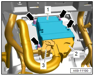
- Remove the nuts -arrows-.
 WARNING
Before handling pyrotechnic components (for example, disconnecting the connector), the person handling it must "discharge static electricity". This can be done by briefly touching the door striker pin, for example.
- Carefully lift the airbag control module -1- from the threaded pins and remove it.
- Disconnect the connectors -2 and 3- by releasing the connector safety catch and securing clip on the connector.
Installing
 WARNING
- Follow all safety precautions when working on pyrotechnic components. Refer to → Chapter "Safety Precautions for Pyrotechnic Components".
- Before handling pyrotechnic components (for example, connecting the connector), the person handling it must "discharge static electricity". This can be done by briefly touching the door striker pin, for example.
Install in reverse order of removal and note the following:
 Note
Note
Make sure the connectors are pushed in all the way and that they engage audibly.
 WARNING
- After every removal and installation of the Airbag Control Module -J234-, the Guided Function "Inertial sensor basic setting" must be performed.
- If the Airbag Control Module - J234- is replaced with a new part, the basic setting within operation must be performed using the "15 - Replace airbag control module" program.
- If the Airbag Control Module - J234- is removed and then the same one is reinstalled, perform the "Inertial sensor basic setting" as described in the following:
- Connect the Vehicle Diagnostic Tester.
- Switch the ignition on.
- Select and start the Diagnostic operating mode.
- Select the Test plan tab.
- Select the button Individual tests and select the following tree structures one after the other:
- Body
- Body Assembly
- 01 - OBD-capable systems
- 15 - Airbag - J234
- 15 - Airbag, Functions
- 15 - Basic Setting
- 15 - Inertial Sensor Basic Setting
- Start the selected program and follow the instructions in the display of the Vehicle Diagnostic Tester.
 WARNING
Repairing pyrotechnic components (for example the airbag and seat belt tensioner) incorrectly increases the risk of unintentional deployments when the battery is connected.
- The ignition must be on when connecting the battery.
- For personal safety when connecting the battery, stay out of the deployment area of the airbag and maintain a distance from the seat belt tensioners/seat belts.
- Make sure that there are no other people inside the vehicle at the time when the battery is connected.
- Connect the battery ground cable with the ignition turned on. Refer to → Electrical Equipment; Rep. Gr.27; Battery; Battery, Disconnecting and Connecting.
 Note
Note- If the Airbag Indicator Lamp -K75- signals a fault after installing, check the Diagnostic Trouble Code (DTC) memory, erase it and check it again use the Vehicle Diagnostic Tester.
- The Airbag Control Module -J234- must be coded after replacing it using the Vehicle Diagnostic Tester.
Installation notes, for example tightening specifications, replacing components. Refer to → Chapter "Overview - Airbag Control Module".

