Audi Q7: Backrest Adjuster, Removing and Installing
Backrest Adjustment Hand Wheel, Removing and Installing
Special tools and workshop equipment required
- Assembly Tool -3399-
Removing
- Move the front seat all the way forward into its highest position.
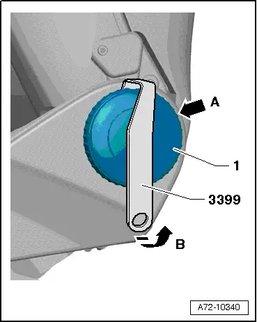
- Turn the backrest adjustment wheel -1- until one catch is visible from behind -arrow A-. If necessary use a flashlight.
- Attach the -3399- to the catch and pry off the hand wheel -arrow B-.
- Turn the backrest adjustment hand wheel 120º farther and repeat the process.
- Remove the backrest adjustment hand wheel.
Installing
Install in reverse order of removal.
Installation notes, for example tightening specifications, replacing components. Refer to → Chapter "Overview - Seat Pan, Trim Panels".
Driver and Front Passenger Backrest Adjustment Motor -V45-/-V46-, Removing and Installing
Special tools and workshop equipment required
- Engine/Transmission Holder - Seat Repair Fixture -VAS6136-
Removing
 WARNING
- Follow all safety precautions when working on pyrotechnic components. Refer to → Chapter "Safety Precautions for Pyrotechnic Components".
- Before handling airbag units (for example, disconnecting the connector), the person handling it must "discharge static electricity". For example, this can be done by briefly touching the door striker.
- Remove the front seat. Refer to → Chapter "Front Seat, Removing and Installing".
- Fasten the front seat on the -VAS6136-. Refer to → Chapter "Front Seat, Mounting on Fixture for Seat Repair".
- Remove the tunnel-side seat side trim. Refer to → Chapter "Seat Side Trim on Tunnel Side, Removing and Installing".
- Remove the seat side trim on the side sill side. Refer to → Chapter "Seat Side Trim On Side Sill Side, Removing and Installing".
- Remove the backrest cover. Refer to → Chapter "Backrest Cover, Removing and Installing".
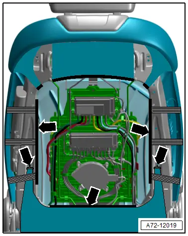
- Disengage the molding for the cover and both hooks -arrows-, and pull the cover back.
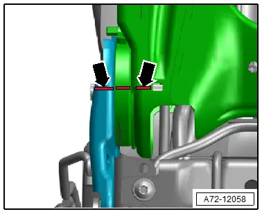
- Mark the left and right angle position of the backrest hinge to the backrest frame with paint -arrows-.
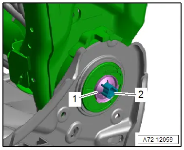
- Destroy the lock washer -1- and remove it.
- Push the adjustment shaft -2- to the opposite side out of the backrest frame.
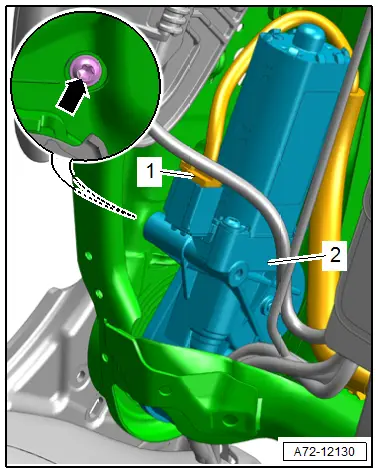
- Remove the bolt -arrow- and remove the backrest adjustment motor -2-.
- Disconnect the connector -1- from the removed backrest adjustment motor.
Installing
 WARNING
- Follow all safety precautions when working on pyrotechnic components. Refer to → Chapter "Safety Precautions for Pyrotechnic Components".
- Before handling pyrotechnic components (for example, connecting a connector), the person handling it must "discharge static electricity". For example, this can be done by briefly touching the door striker.
- Follow all the instructions when installing the front seat. Refer to → Chapter "Front Seat, Removing and Installing".

- Check the left and right position of the backrest frame and hinge.
- The backrest frame must be in the position marked on the left and right side before removal -arrows-.
- If the left and right backrest frames are not in the correct position, correct their position accordingly.
- First slide the adjustment shaft through the anchor (tunnel side) as far as the mount in the backrest adjustment motor.
- Check if the profile of the inserted adjustment shaft and the mount in the backrest adjustment motor to see if they align.
- For adjustment, connect an external 12-volt power source to the backrest adjustment motor and turn mount until the profiles of adjustment shaft and mount are aligned.

- Slide the adjuster shaft through the mount in the backrest adjustment motor -2- and slide the hinge (side sill side) until it stops.
- Tighten the bolt -arrow- for the backrest adjustment motor.
- Connect the connector -1- for the backrest adjustment motor.
- Push the lock washer -1- onto the adjustment shaft -2- so that there is still at least 1.0 mm of play.
Further installation is the reverse order of removal.
Installation instructions: for example tightening specifications, replacing components. Refer to → Chapter "Overview - Front Backrest, Backrest Adjustment Motor".


