Audi Q7: Driver Side Instrument Panel Cover, Removing and Installing
Special tools and workshop equipment required
- Trim Removal Wedge -3409-
Removing
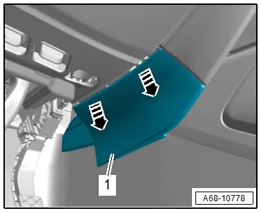
- Unclip the inner driver side cover -1- from the instrument panel cover using the -3409- in direction of -arrows-.
- Remove the driver side instrument panel side cover. Refer to → Chapter "Instrument Panel Side Cover, Removing and Installing".
- Equipped on some models: Remove the footwell lamp. Refer to → Electrical Equipment; Rep. Gr.96; Lamps; Overview - Component Location Instrument Panel Lamps.
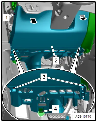
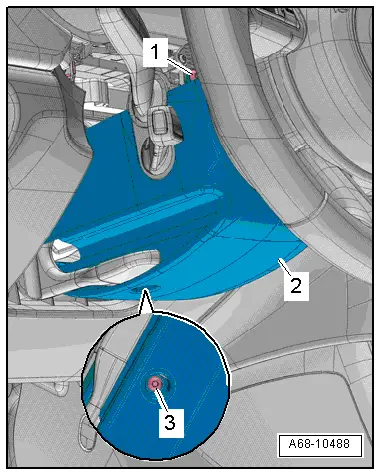
- Remove the side bolt -1-.
- Remove the lower bolts -3-.
- Unclip the driver side instrument panel cover -2- from the instrument panel by hand -arrows-.
- Remove the driver side instrument panel cover from the mount -4-.
- Equipment version: disconnect the connectors for the parking aid and emergency call speaker.
- Disengage the diagnostic connection on the instrument panel cover.
Installing
Install in reverse order of removal.
Installation notes, for example tightening specifications, replacing components. Refer to → Chapter "Overview - Driver Side Instrument Panel Cover".
Upper Steering Column Trim Panel, Removing and Installing
Removing
- Move the steering wheel as far down as possible to do this use the full steering column adjustment range.
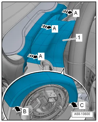
- Unclip the gap cover for the instrument cluster from the instrument cluster trim by hand in direction of -arrows A-.
- Turn the steering wheel counterclockwise 90º from the straight position.
- Pry the upper steering column trim -1- carefully using a small flat-head screwdriver from the lower steering column trim -arrow B-.
- Turn the steering wheel back 180º and repeat the procedure on the opposite side -arrow C-.
- Disengage the upper steering column trim from the lower steering column trim and remove.
Installing
Install in reverse order of removal and note the following:
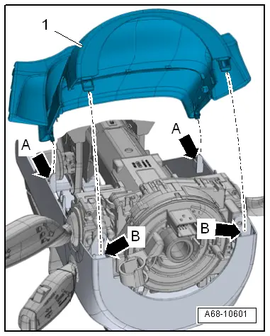
- Engage the upper steering column trim -1- in the lower steering column trim -arrows A-.
- Ensure the steering column trim panel pins engage in the opening at the upper steering column trim panel retaining tab -arrows B-.
Installation notes, for example tightening specifications, replacing components. Refer to → Chapter "Overview - Steering Column Trim Panel".
Lower Steering Column Trim Panel, Removing and Installing
Removing
- Remove the upper steering column trim. Refer to → Chapter "Upper Steering Column Trim Panel, Removing and Installing".
- Turn the steering wheel counterclockwise 90º from the straight position.
- Remove the bolt -1-.
- Turn steering wheel back 180º and remove bolt on the opposite side.
 Note
Note
When bolt -1- is not accessible, the steering wheel must be removed for further work. Refer to → Suspension, Wheels, Steering; Rep. Gr.48; Steering Wheel; Steering Wheel, Removing and Installing.
- Remove the bolt -3- and remove the lower steering column trim panel -2-.
- Disengage the cable holder on the steering column trim panel.
- Disconnect the connector for the Steering Column Adjustment Switch -E167-.
Installing
Install in reverse order of removal.
Installation notes, for example tightening specifications, replacing components. Refer to → Chapter "Overview - Steering Column Trim Panel".

