Audi Q7: Instrument Panel, Removing and Installing
Removing
- Move the steering wheel as far down as possible to do this use the full steering column adjustment range.
- Move the front seats all the way back and tilt backrests 45º.
 WARNING
- Follow all safety precautions when working on pyrotechnic components. Refer to → Chapter "Safety Precautions for Pyrotechnic Components".
- Follow the allocation of the airbag to the instrument panel. Refer to the Parts Catalog.
- Disconnect the battery ground cable with the ignition turned on. Refer to → Electrical Equipment; Rep. Gr.27; Battery; Battery, Disconnecting and Connecting.
- Remove the driver side airbag unit. Refer to → Chapter "Airbag Unit with Igniter, Removing and Installing".
- Remove the steering wheel. Refer to → Suspension, Wheels, Steering; Rep. Gr.48; Steering Wheel; Steering Wheel, Removing and Installing.
- Remove the upper steering column trim. Refer to → Chapter "Upper Steering Column Trim Panel, Removing and Installing".
- Remove the lower steering column trim panel. Refer to → Chapter "Lower Steering Column Trim Panel, Removing and Installing".
- Remove the steering column switch. Refer to → Electrical Equipment; Rep. Gr.94; Steering Column Switch Module; Steering Column Switch Module, Removing and Installing.
- Remove the center console support. Refer to → Chapter "Center Console Support, Removing and Installing".
- Remove the instrument panel side cover. Refer to → Chapter "Instrument Panel Side Cover, Removing and Installing".
- Remove the instrument panel cover on the driver side. Refer to → Chapter "Driver Side Instrument Panel Cover, Removing and Installing".
- Remove the light switch trim. Refer to → Chapter "Light Switch Trim, Removing and Installing".
- Remove the glove compartment. Refer to → Chapter "Glove Compartment, Removing and Installing".
- Remove A/C display control head trim. Refer to → Chapter "Display Control Head Trim, Removing and Installing".
- Remove the instrument panel decorative trim on the driver side, the front passenger side and in the center. Refer to → Chapter "Instrument Panel Decorative Trim, Removing and Installing".
- Remove the access/start authorization switch trim. Refer to → Chapter "Access/Start Authorization Switch Trim, Removing and Installing".
- Remove the driver and front passenger instrument panel vent. Refer to → Chapter "Instrument Panel Vent, Removing and Installing".
- Remove the instrument cluster trim. Refer to → Chapter "Instrument Cluster Trim, Removing and Installing".
- Remove the instrument cluster. Refer to → Electrical Equipment; Rep. Gr.90; Instrument Cluster; Overview - Instrument Cluster.
- Remove the MMI screen cover. Refer to → Chapter "MMI Screen Cover, Removing and Installing".
- Remove the Infotainment system display. Refer to → Communication; Rep. Gr.91; Infotainment System; Component Location Overview - Infotainment System.
- Remove the speaker trim from the instrument panel. Refer to → Chapter "Speaker Trim, Removing and Installing".
- Remove the speaker in the instrument panel. Refer to → Communication; Rep. Gr.91; Sound System; Component Location Overview - Sound System.
- Remove the A-pillar upper trim panels. Refer to → Chapter "A-Pillar Upper Trim Panel, Removing and Installing".
- Remove the Sunlight Photo Sensor -G107-. Refer to → Heating, Ventilation, and Air Conditioning; Rep. Gr.87; Additional Components for Control and Regulation; Sunlight Photo SensorG107 Removing and Installing.
- Remove the air duct to the center instrument panel vents. Refer to → Heating, Ventilation and Air Conditioning; Rep. Gr.87; Air Duct; Overview - Air Routing and Air Distribution in Vehicle Interior.
- Remove the air duct to the right instrument panel vent and to the wide vent. Refer to → Heating, Ventilation and Air Conditioning; Rep. Gr.87; Air Duct; Overview - Air Routing and Air Distribution in Vehicle Interior.
 WARNING
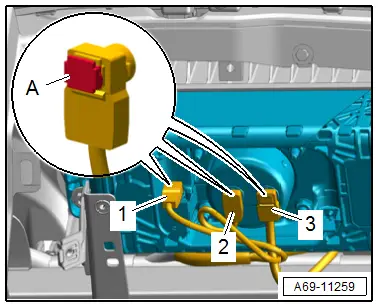
Before handling pyrotechnic components (for example, disconnecting the connector), the person handling it must "discharge static electricity". This can be done by briefly touching the door striker pin, for example.
- Disconnect the connectors -1, 2 and 3- for the front passenger side airbag unit.
- Release the connector lock -A- using a small screwdriver.
- Equipped on some models: remove the windshield projection trim (Head up display). Refer to → Chapter "Windshield Projection (Head-Up Display) Trim, Removing and Installing".
- Remove the instrument panel bolts -arrows- on the driver side central tube and in the center.
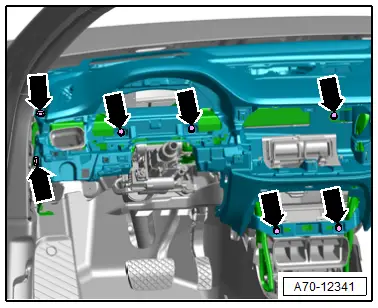
- Remove the instrument panel bolts -arrows- on the front passenger side central tube.
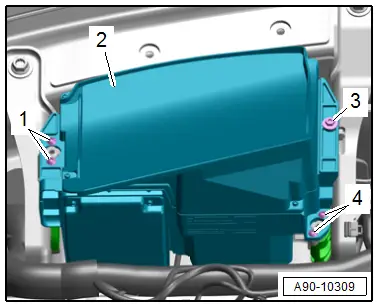
- Equipped on some models: remove the screws -1, 3 and 4- and remove the Windshield Projection Head Up Display Control Module -J898- loosely toward the rear with the instrument panel.
- Lift out the control module -2- slightly and disconnect the connector.
 Note
Note
Two technicians are needed to remove the instrument panel.
- Unclip and free up the wiring harnesses from the instrument panel.
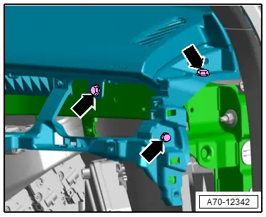
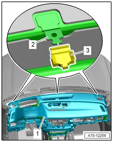
- Lift the instrument panel -1- slightly and carefully remove toward the rear from the mount -2- and from the central tube.
- Remove the instrument panel carefully toward the rear while guiding the connectors out.
- Remove the instrument panel from the vehicle interior and lay it on a soft surface.
Installing
Install in reverse order of removal and note the following:
 WARNING
Follow the allocation of the airbag to the instrument panel. Refer to the Parts Catalog.
- Set the instrument panel in place and guide the connectors through the openings in the instrument panel.
- Check if there is a rubber buffer -3- on the instrument panel mount -2- on the lower windshield frame.
- When sliding on the instrument panel -1-, make sure the instrument panel mounts engage in the box-shaped profiles on the bottom side of the instrument panel.
 WARNING
- Follow all safety precautions when working on pyrotechnic components. Refer to → Chapter "Safety Precautions for Pyrotechnic Components".
- Before handling pyrotechnic components (for example, connecting the connector), the person handling it must "discharge static electricity". This can be done by briefly touching the door striker pin, for example.
 Note
Note
Make sure the connectors are installed all the way and engage audibly.
 WARNING
The ignition must be on when connecting the battery. If pyrotechnic components (for example, airbag, belt tensioner) are not repaired correctly, they may deploy unintentionally after connecting battery. There must not be anyone in the vehicle interior when connecting the battery.
- Connect the battery ground cable with the ignition turned on. Refer to → Electrical Equipment; Rep. Gr.27; Battery; Battery, Disconnecting and Connecting.
 Note
Note
If the Airbag Indicator Lamp -K75- indicates a fault, check the Diagnostic Trouble Code (DTC) memory, erase it and check it again using the Vehicle Diagnostic Tester.
Installation notes, for example tightening specifications, replacing components. Refer to → Chapter "Overview - Instrument Panel".
Display Control Head Trim, Removing and Installing
Special tools and workshop equipment required
- Wedge Set -T10383-
Removing
- Move the steering wheel as far up and backward as possible to be able to use the full steering column adjustment range.
- Remove the instrument panel cover on the driver side. Refer to → Chapter "Driver Side Instrument Panel Cover, Removing and Installing".
- Remove the front passenger side instrument panel side cover. Refer to → Chapter "Instrument Panel Side Cover, Removing and Installing".
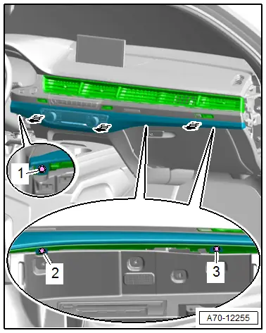
- Remove the bolt -1-.
- Open the glove compartment cover and remove the screws -2 and 3-.
- Unclip the trim with the A/C display control head using the -T10383/1--arrows-.
- Disconnect the connectors and remove the trim with the A/C display control head.
Installing
Install in reverse order of removal.
Installation notes, for example tightening specifications, replacing components. Refer to → Chapter "Overview - Instrument Panel".
Speaker Mount, Removing and Installing
Special tools and workshop equipment required
- Trim Removal Wedge -3409-
- Wedge Set -T10383-
Center Speaker Mount, Removing
- Remove the speaker trim. Refer to → Chapter "Speaker Trim, Removing and Installing".
- If installed, remove the speaker. Refer to → Communication; Rep. Gr.91; Sound System; Component Location Overview - Sound System.
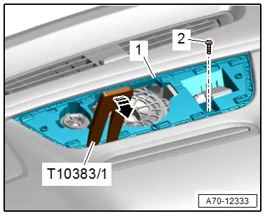
- Remove the bolt -2-.
- Disengage the speaker mount -1- using the -T10383/1--arrow-.
- Disengage the remaining retainers for the speaker mount and remove.
Outer Speaker Mount, Removing
- Remove the speaker trim. Refer to → Chapter "Speaker Trim, Removing and Installing".
- If installed, remove the speaker. Refer to → Communication; Rep. Gr.91; Sound System; Component Location Overview - Sound System.
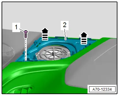
- Remove the bolt -1-.
- Disengage the speaker mount -2- using the -3409- in direction of -arrows-.
Installing
Install in reverse order of removal.
Installation notes, for example tightening specifications, replacing components. Refer to → Chapter "Overview - Instrument Panel".

