Audi Q7: Plenum Chamber Bulkhead, Removing and Installing
Plenum Chamber Bulkhead, Removing and Installing
Removing
- Drain the coolant. Refer to → Engine Mechanical; Rep. Gr.19; Cooling System/Coolant; Coolant, Draining and Filling.
- Remove the plenum chamber cover. Refer to → Chapter "Plenum Chamber Cover, Removing and Installing".
- Remove the tower brace. Refer to → Suspension, Wheels, Steering; Rep. Gr.40; Suspension Strut, Upper Control Arm; Tower Brace, Removing and Installing.
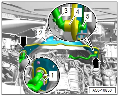
- Remove the vacuum hoses -3 and 5- on both sides from the grommet -4-.
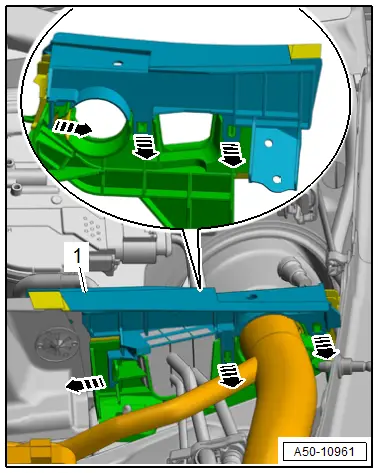
- Loosen the hose clamps -1-, remove the coolant hoses and free them up.
- Remove the bolts -arrows-.
- Remove the plenum chamber bulkhead -2- upward.
Installing
Install in reverse order of removal and note the following:
- Fill the coolant. Refer to → Engine Mechanical; Rep. Gr.19; Cooling System/Coolant; Coolant, Draining and Filling.
Tightening Specifications
- Refer to → Chapter "Overview - Bulkhead"
Plenum Chamber Bulkhead, Removing and Installing, Vehicles with High-Voltage System
Removing
- Drain the coolant. Refer to → Engine Mechanical; Rep. Gr.19; Cooling System/Coolant; Coolant, Draining and Filling.
- Remove the plenum chamber cover. Refer to → Chapter "Plenum Chamber Cover, Removing and Installing".
- Remove the tower brace. Refer to → Suspension, Wheels, Steering; Rep. Gr.40; Suspension Strut, Upper Control Arm; Tower Brace, Removing and Installing.
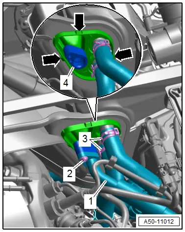
- Loosen the hose clamps -3-, remove the coolant hoses and free them up.
- Remove the bolt -2-.
- Remove the refrigerant line -1- from the connection at the connection location.
- Release the retainers -arrows- and press the pass-through -4- out of the plenum chamber bulkhead.
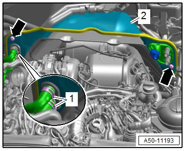
- Loosen the hose clamps -1-, remove the coolant hoses and free them up.
- Remove the bolts -arrows-.
- Remove the plenum chamber bulkhead -2- upward.
Installing
Install in reverse order of removal and note the following:
- Fill the coolant. Refer to → Engine Mechanical; Rep. Gr.19; Cooling System/Coolant; Coolant, Draining and Filling.
Tightening Specifications
- Refer to → Chapter "Overview - Bulkhead"
Plenum Chamber End Plate, Removing and Installing
Removing
- Remove the upper cover for the plenum chamber end plate. Refer to → Chapter "Plenum Chamber End Plate Upper Cover, Removing and Installing".
- Remove the additional reinforcement for the tower brace. Refer to → Suspension, Wheels, Steering; Rep. Gr.40; Suspension Strut, Upper Control Arm; Tower Brace Removing and Installing.
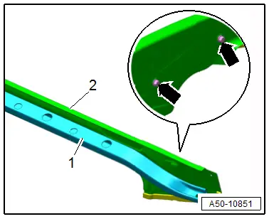
- Remove the bolts -arrows-.
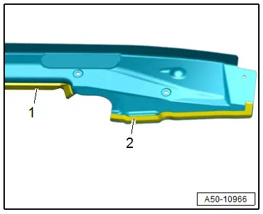
- Remove the plenum chamber end plate -2- from the additional reinforcement -1-.
Installing
Install in reverse order of removal and note the following:
- Check the seals -1 and 2- for damage.
Tightening Specifications
- Refer to → Chapter "Overview - Bulkhead"
Plenum Chamber End Plate Upper Cover, Removing and Installing
Removing
- Remove the rear cover for the fender. Refer to → Chapter "Rear Fender Cover, Removing and Installing".
- Release the retainers -arrows-.
- Remove cover -1- upward.
Installing
Install in reverse order of removal.

