Audi Q7: Seat Height Adjuster, Removing and Installing
Seat Height Adjuster, Removing and Installing, Seat Height Adjustment Handle
Special tools and workshop equipment required
- Trim Removal Wedge -3409-
Removing
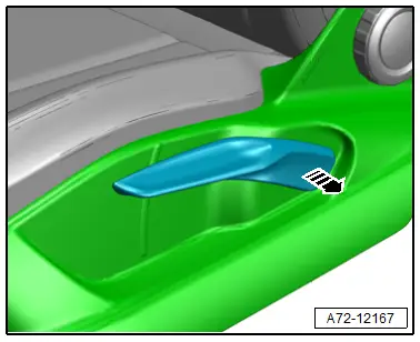
- Remove the seat height adjustment handle -1- from the seat toward the side -arrow-.
Installing
Install in reverse order of removal.
Installation notes, for example tightening specifications, replacing components. Refer to → Chapter "Overview - Seat Pan, Trim Panels".
Upper Frame, Removing and Installing, Seat Height Adjustment Motor
Mandatory Replacement Parts
- Bolts - Seat Pan to Upper Frame
Special tools and workshop equipment required
- Engine/Transmission Holder - Seat Repair Fixture -VAS6136-
 Note
Note
- The Driver Seat Height Adjustment Motor -V245-/Front Passenger Seat Height Adjustment Motor -V246- is integrated in the seat pan upper frame. The seat height adjustment motor cannot be replaced separately.
- To replace, install all electrical and electronic components and wires in the new upper frame.
Removing
 WARNING
- Follow all safety precautions when working on pyrotechnic components. Refer to → Chapter "Safety Precautions for Pyrotechnic Components".
- Before handling pyrotechnic components (for example, disconnecting the connector), the person handling it must "discharge static electricity". For example, this can be done by briefly touching the door striker.
- Move the front seat to the highest position possible to keep the torsion bar tension as low as possible.
- Remove the front seat. Refer to → Chapter "Front Seat, Removing and Installing".
- Fasten the front seat on the -VAS6136-. Refer to → Chapter "Front Seat, Mounting on Fixture for Seat Repair".
- Remove the backrest. Refer to → Chapter "Front Backrest, Removing and Installing".
- Remove the cushion. Refer to → Chapter "Seat Pan Cover and Cushion, Removing and Installing, Seat with Seat Depth Adjuster".
- Remove the bracket for the front trim. Refer to → Chapter "Front Seat Trim Bracket, Removing and Installing".
- Remove the seat depth adjuster. Refer to → Chapter "Seat Depth Adjuster, Removing and Installing".
- Remove the seat angle adjuster. Refer to → Chapter "Seat Angle Adjuster, Removing and Installing".
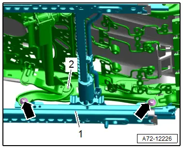
- Remove the front and rear bolts -arrows- on the left and right side.
- Remove the seat pan upper frame -2- from the lower frame -1- and place it on a clean surface.
 Caution
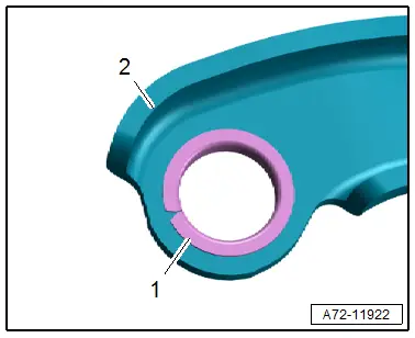
Risk of damaging the bushings -1- in the bearing points -2- (upper/lower frame bolted connection).
- The bushings cannot be replaced with workshop materials.
- If the bushings are damaged, the corresponding parts must be replaced.
Installing
 WARNING
- Follow all safety precautions when working on pyrotechnic components. Refer to → Chapter "Safety Precautions for Pyrotechnic Components".
- Before handling pyrotechnic components (for example, connecting a connector), the person handling it must "discharge static electricity". For example, this can be done by briefly touching the door striker.
- Follow all the instructions when installing the front seat. Refer to → Chapter "Front Seat, Removing and Installing".
Install in reverse order of removal and note the following:
- If the seat pan upper frame is being replaced, reposition the attachments.
Installation instructions: for example tightening specifications, replacing components. Refer to → Chapter "Overview - Seat Pan, Seat Forward/Back and Height Adjustment".
Seat Angle Adjuster, Removing and Installing
 Caution
This procedure contains mandatory replaceable parts. Refer to component overview prior to starting procedure.
Mandatory Replacement Parts
- Bolt - Driver Seat Angle Adjustment Motor to Adjustment Shaft
Removing
- Move the front seat into its highest position.
- Unscrew the front seat and tip to the rear with the wires attached. Refer to → Chapter "Front Seat, Removing and Installing".
 Caution
Risk of damage to the bushing in the bearing point (adjusting spindle/seat pan threaded connection -1-).
- The bushing cannot be replaced with workshop materials.
- If the bushing is damaged, the corresponding assembly parts must be replaced.
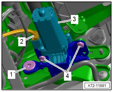
- Remove the bolt -1- for the seat angle adjustment motor adjusting spindle.
- Disconnect the connector -2- on the seat angle adjustment motor.
- Remove the bolts -4- and remove the seat angle adjuster motor -3-.
Installing
Install in reverse order of removal.
Installation notes, for example tightening specifications, replacing components. Refer to → Chapter "Overview - Seat Pan, Seat Angle Adjuster".

