Audi Q7: Charge Door Unit
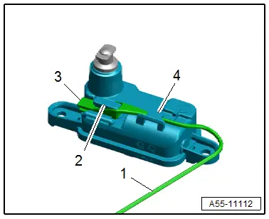
Overview - Charge Door Unit
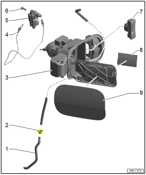
1 - Drain Hose
- For the charge door unit
- Removing and Installing. Refer to → Chapter "Charge Door Unit Drain Hose, Removing and Installing".
2 - Grommet
3 - Charge Door Unit
- Removing and Installing. Refer to → Chapter "Charge Door Unit, Removing and Installing".
4 - Cable
- For the charge door lock
- Removing and Installing. Refer to → Chapter "Cable for High-Voltage Charge Door Lock, Removing and Installing".
5 - High-Voltage Charge Door Lock 1 Adjuster -F496-
- Removing and Installing. Refer to → Chapter "High-Voltage Charge Door Lock 1 Adjuster -F496-, Removing and Installing".
6 - Bolt
- 1.5 Nm
- Quantity: 2
7 - Battery Charging Button Module -EX32-
- with Charging Socket LED Module 1 -L263-, Immediate Charging Button -E766-, Charging Profile Selection Button -E808-
- Overview. Refer to → Electric Drive; Rep. Gr.93; Charging Socket; Overview - Charging Socket
8 - Information Label
- On the charge door unit
9 - Charge Door Unit Trim
- Removing and Installing. Refer to → Chapter "Charge Door Unit Trim, Removing and Installing".
Charge Door Unit, Removing and Installing
Removing
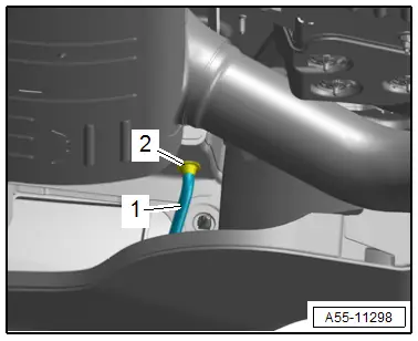
- Grab behind the wheel housing liner and push the grommet -2- for the drain hose -1- inward.
- Remove the luggage compartment left trim panel. Refer to → Body Interior; Rep. Gr.70; Luggage Compartment Trim Panels; Luggage Compartment Side Trim Panel, Removing and Installing.

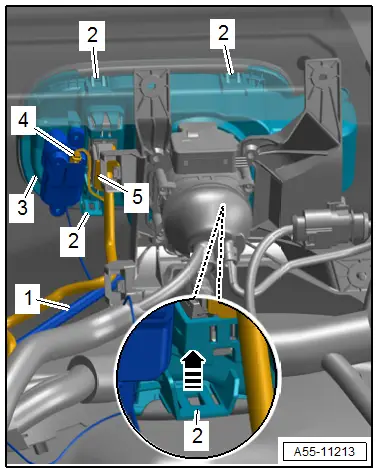
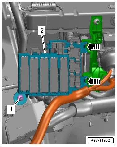
- Remove the nut -1-.
- Release the retainers -arrows-.
- Remove fuse panel F -item 2- to the right.

- Disconnect the connectors -4 and 5-.
- Remove the charge door trim. Refer to → Chapter "Fuel Filler Door Unit Trim, Removing and Installing".
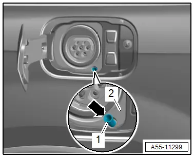
- Remove the protective cover for the charging socket.
- Open the retainers -2--arrow-.
- Remove the charge port door -3-, while guiding out the emergency release cable and drain hose -1- at the same time.
Installing
Install in reverse order of removal and note the following:
- Insert the hinge side of the charge door unit first into the charge door opening and push it in until it clicks into place.
- Check that the boot sits correctly in the charging socket mount.
Tightening Specifications
- Refer to → Electrical Equipment; Rep. Gr.97; Relay Panels, Fuse Panels, E-Boxes; Component Location Overview - Relay Panels, Fuse Panels, E-Boxes.
Charge Door Unit Trim, Removing and Installing
Removing
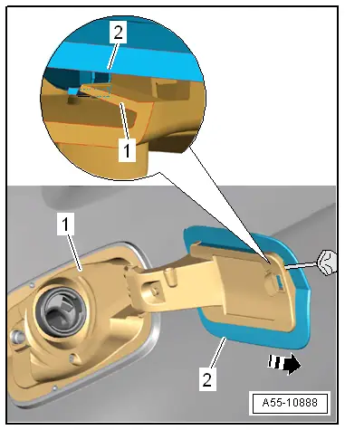
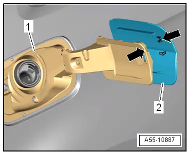
- Open the charge door.
- Release the clips with a screwdriver in the gap between the trim -2- and the charge door -1-.
- Pull the trim slightly toward the rear from the charge door -arrow- and remove it.
Installing
Install in reverse order of removal and note the following:
- The guides on the trim -2- must be positioned behind the mounts -arrows- when placing on the charge door -1-.
- Slide the trim forward until the clips audibly engage.
Charge Door Unit Drain Hose, Removing and Installing
Removing
- Grab behind the wheel housing liner and push the grommet -2- for the drain hose -1- inward.
- Remove the luggage compartment left trim panel. Refer to → Body Interior; Rep. Gr.70; Luggage Compartment Trim Panels; Luggage Compartment Side Trim Panel, Removing and Installing.
- Remove the nut -1-.
- Release the retainers -arrows-.
- Remove fuse panel F -item 2- to the right.
- Remove the drain hose upward from the charge door unit.
Installing
Install in reverse order of removal and note the following:
- Insert the drain hose -1- from above into the charge door cup -2-.
- The collar -arrow- on the drain hose must be on top.
- Insert the drain hose grommet into the body.
Tightening Specifications
- Refer to → Electrical Equipment; Rep. Gr.97; Relay Panels, Fuse Panels, E-Boxes; Component Location Overview - Relay Panels, Fuse Panels, E-Boxes.
Cable for High-Voltage Charge Door Lock, Removing and Installing
Removing
- High-voltage charge door lock adjuster. Refer to → Chapter "High-Voltage Charge Door Lock 1 Adjuster -F496-, Removing and Installing"
- Thread the cable -1- out of the guide -4-.
- Disengage the tab -3- on the emergency release mount -2- and remove it from the cable bracket.
Installing
Install in reverse order of removal.
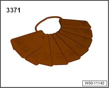
Special Tools
Special tools and workshop equipment required
- Gauge - Gap Adjustment -3371-