Audi Q7: Control Module, Separating from Hydraulic Unit
Special tools and workshop equipment required
- ESD Work Surface -VAS6613-
 Note
Note
- If the ABS Control Module -J104- is faulty it can be replaced separately.
- If the ABS Hydraulic Unit -N55- is faulty it must be replaced together with the ABS Control Module -J104-.
 Note
Note
The ABS Hydraulic Unit -N55- with the ABS Control Module -J104- must be removed in order to separate the control module and the hydraulic unit.
 Caution
Risk of destroying the hydraulic unit.
- The return flow pump may not be removed from the ABS Hydraulic Unit -N55-.
- If the ABS Control Module -J104- is removed the circuit board is in the open.
- Moisture and dirt must not enter the control module.
- Avoid electrostatic charge. It can cause malfunctions in the electronic components if contact is made.
- The seal on the control module must not be pulled out or raised up.
- Blowing the control module or hydraulic unit with compressed air is not permitted.
- The valve bodies inside the hydraulic unit must not be damaged or bent.
Procedure
- Remove the hydraulic control unit. Refer to → Chapter "ABS Control Module -J104-/ABS Hydraulic Unit -N55-, Removing and Installing".
 Caution
There is a risk of destroying the hydraulic unit.
- Before disconnecting the components touch a grounded object (ESD Work Surface -VAS6613-.
- Do not touch the connector terminals or electronic components directly.
- Place the hydraulic unit with the control module on the ESD Work Surface -VAS6613-.
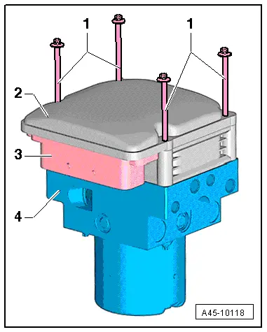
- The control module -2- faces upward and the hydraulic unit -4- with the pump motor and connector -3- faces down.
- Remove the bolts -1- and dispose of them.
- Remove the control module vertically upward without tilting.
- Cover the open hydraulic unit with a lint-free cloth.
- Check the hydraulic unit sealing surface if necessary clean with mineral spirits and a lint-free cloth.
- A damaged sealing surface must not be mechanically reworked. A hydraulic unit with a damaged sealing surface must be replaced.
 Caution
There is a risk of destroying the hydraulic unit.
The seal must not be pulled out or raised up. The seal cannot be replaced.
Control Module, Installing on Hydraulic Unit
Special tools and workshop equipment required
- Torque Screwdriver -VAG1624-
- ESD Work Surface -VAS6613-
- Torx insert T25
Procedure
 Note
Note
Use the complete repair kit when installing.
 Caution
There is a risk of destroying the ABS control module.
Protect the control module from bumps or impact. A control module that has fallen to the ground can no longer be used.
- The hydraulic unit -4- with the pump motor and the connector -3- faces down.
- Place the hydraulic unit -2- carefully without tilting from above on the hydraulic unit.
- Install the new bolts -1- by hand until the control module touches the hydraulic unit evenly.
 Note
Note
If the bolts for the control module on the hydraulic unit are difficult to install or cannot be tightened to the tightening specification the hydraulic unit must be replaced.
- Tighten the bolts in two stages in a diagonal sequence.
- Install the hydraulic control unit. Refer to → Chapter "ABS Control Module -J104-/ABS Hydraulic Unit -N55-, Removing and Installing".
- After installing the hydraulic control unit and the brake system is bled select the function "Replacing" for the ABS Control Module -J104-/ABS Hydraulic Unit -N55-. Refer to Vehicle Diagnostic TesterGuided Functions.
 WARNING
Risk of accident!
Make sure the brakes are working correctly before driving the vehicle for the first time.

Tightening Specifications
- Refer to → Chapter "Overview - Control Module and Hydraulic Unit"

