Audi Q7: General Information
 Note
Note
- On this vehicle the brake system is divided by axle.
- Right and left front axle
- Right and left rear axle
Anti-Lock Braking System (ABS) Repair Information
 Note
Note
ABS malfunctions do not affect the brake system and the booster. The conventional brake system remains operative even without ABS. A change in braking behavior should be checked. When the ABS indicator lamp comes on the rear wheels can lock-up early when braking!
 WARNING
- The ABS is generally maintenance-free.
- Testing, assembly, and repair work may only be performed by qualified personnel.
- By not observing the points described in the repair manual, the system can be damaged and vehicle safety could be compromised.
- Before performing repair work on the ABS system, determine the cause of the damage using OBD.
- Disconnect the battery ground cable when the ignition is switched off.
- When handling brake fluid, observe the relevant safety precautions and notes. Refer to → Chapter "Brake Fluid General Information".
- Bleed the brake system with the Brake Charger/Bleeder Unit -VAS5234- for all work that requires opening the hydraulic system. High and low pressure testing should also be performed on the brake system.
- During the final road test, ensure that a ABS-controlled brake test is performed at least once (pulsation must be felt at the brake pedal).
Component Location Overview
Component Location Overview - ABS/ESP
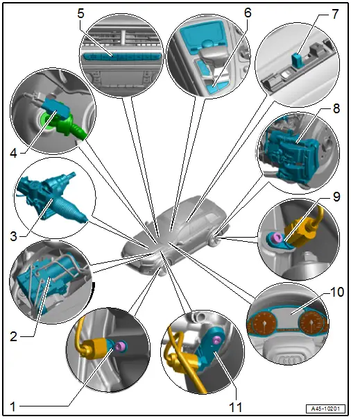
1 - Front Speed Sensor
- Left Front ABS Wheel Speed Sensor -G47-
- Right Front ABS Wheel Speed Sensor -G45-
- Overview. Refer to → Chapter "Overview - Front Axle Speed Sensor".
2 - Hydraulic Control Unit
- With
- ABS Control Module -J104-
- ABS Hydraulic Unit -N55-
- The control module and the hydraulic unit can be separated
- Overview. Refer to → Chapter "Overview - Control Module and Hydraulic Unit".
3 - Steering Angle Sensor -G85-
- Integrated in the Steering Column Switch Module
- Cannot be replaced separately
- If faulty replace the steering gear. Refer to →Electrical Equipment; Rep. Gr.94.
4 - Vacuum Sensor -G608-
5 - Switch Module in Instrument Panel, Center -EX22-
- With
- ASR/ESP Button -E256-
- Hill Descent Control Button -E618- (equipment level)
- Removing and installing. Refer to → Electrical Equipment; Rep. Gr.96; Controls; Component Location Overview - Controls in Center Console.
6 - Electromechanical Parking Brake Button -E538-
- Electromechanical Parking Brake Button -E538-
- -AUTO HOLD- Button -E540- (equipment level)
- Removing and installing. Refer to → Electrical Equipment; Rep. Gr.96; Controls; Electromechanical Parking Brake Button E538/-AUTO HOLD- ButtonE540, Removing and Installing.
7 - Roof Rack Recognition Sensor -G625-
- Component location: in the roof railing
8 - Brake Pad Wear Sensor
- Left Front Brake Pad Wear Sensor -G34-
- Right Front Brake Pad Wear Sensor -G35-
- Left Rear Brake Pad Wear Sensor -G36-
- Right Rear Brake Pad Wear Sensor -G37-
- Actually in the inner brake pad.
- Overview. Refer to → Chapter "Overview - Front Brakes", and → Chapter "Overview - Rear Brakes".
9 - Rear Speed Sensor
- Right Rear ABS Wheel Speed Sensor -G44-
- Left Rear ABS Wheel Speed Sensor -G46-
- Overview. Refer to → Chapter "Overview - Rear Axle Speed Sensor".
10 - Instrument Cluster with Instrument Cluster Control Module -J285-
- With the following integrated indicator lamps:
- ABS Indicator Lamp -K47-
- Brake System Indicator Lamp -K118-
- Parking Brake Indicator Lamp -K139-
- The indicator lamps cannot be replaced separately
- Replace the instrument cluster if faulty. Refer to → Electrical Equipment; Rep. Gr.90; Instrument Cluster; Overview - Instrument Cluster.
11 - Brake Lamp Switch -F-
- Component location: on the brake master cylinder
- Overview. Refer to → Chapter "Overview - Brake Booster/Brake Master Cylinder".

