Audi Q7: Overview - Rear Bumper Cover
Overview - Bumper Cover, Vehicles without High-Voltage System
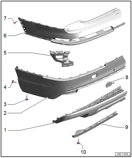
1 - Bumper Cover Lower Section
- There are different versions. Refer to the Parts Catalog .
- Removing and Installing. Refer to → Chapter "Bumper Cover Lower Section, Removing and Installing".
- Bumper cover mount. Refer to → Chapter "Overview - Bumper Cover Mount".
2 - Bumper Cover Lower Section
- Removing and Installing. Refer to → Chapter "Bumper Cover Lower Section, Removing and Installing".
3 - Bolt
- 2.5 Nm
- Quantity: 2
4 - Bolt
- 2.5 Nm
5 - Mount
- for lane change assistance control module
6 - Bumper Cover Upper Section
- Removing and Installing. Refer to → Chapter "Bumper Cover Upper Section, Removing and Installing".
- Bumper cover mount. Refer to → Chapter "Overview - Bumper Cover Mount".
7 - Bolt
- 2.5 Nm
- Quantity: 2
8 - Cap
- for the tail lamp bolt
9 - Spoiler
- Removing and Installing. Refer to → Chapter "Spoiler, Removing and Installing".
10 - Bolt
- 2.5 Nm
- Quantity: 4
Overview - Bumper Cover, S Line Vehicles without High-Voltage System
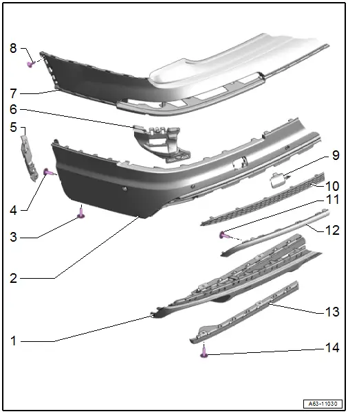
1 - Bumper Cover Lower Section
- There are different versions. Refer to the → Electronic Parts Catalog (ETKA).
- Removing and Installing. Refer to → Chapter "Bumper Cover Lower Section, Removing and Installing, S Line Vehicles".
2 - Bumper Cover Lower Section
- Removing and Installing. Refer to → Chapter "Bumper Cover Lower Section, Removing and Installing".
- Bumper cover mount. Refer to → Chapter "Overview - Bumper Cover Mount".
3 - Bolt
- 2.5 Nm
- Quantity: 2
4 - Bolt
- 2.5 Nm
- Quantity: 2
5 - Intermediate Piece
- For securing the wheel housing liner
6 - Mount
- for lane change assistance control module
7 - Bumper Cover Upper Section
- Removing and Installing. Refer to → Chapter "Bumper Cover Upper Section, Removing and Installing".
- Bumper cover mount. Refer to → Chapter "Overview - Bumper Cover Mount".
8 - Bolt
- 2.5 Nm
- Quantity: 2
9 - Cap
- for the tail lamp bolt
10 - Trim
- For the bumper cover
- Removing and Installing. Refer to → Chapter "Bumper Cover Trim, Removing and Installing".
11 - Bolt
- 2 Nm
12 - Trim Molding
- For the bumper cover
- Removing and Installing. Refer to → Chapter "Bumper Cover Trim Molding, Removing and Installing, S Line Vehicles".
13 - Spoiler
- Removing and Installing. Refer to → Chapter "Spoiler, Removing and Installing".
14 - Bolt
- 2.5 Nm
- Quantity: 4
Overview - Bumper Cover, Vehicles with High-Voltage System
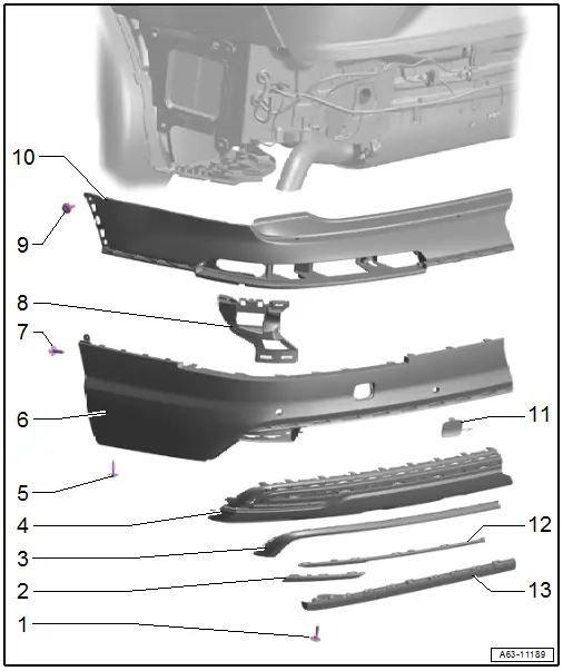
1 - Bolt
- 2.5 Nm
- Quantity: 4
2 - Lower Trim Molding
- For the bumper cover lower section
- Removing and Installing. Refer to → Chapter "Bumper Cover Trim Molding, Removing and Installing, Vehicles with High-Voltage System".
3 - Upper Trim Molding
- For the bumper cover lower section
- Removing and Installing. Refer to → Chapter "Bumper Cover Trim Molding, Removing and Installing, Vehicles with High-Voltage System".
4 - Bumper Cover Lower Section
- There are different versions. Refer to the Parts Catalog.
- Removing and Installing. Refer to → Chapter "Bumper Cover Lower Section, Removing and Installing, S Line Vehicles".
5 - Bolt
- 2.5 Nm
- Quantity: 2
6 - Bumper Cover Lower Section
- Removing and Installing. Refer to → Chapter "Bumper Cover Lower Section, Removing and Installing".
- Bumper cover mount. Refer to → Chapter "Overview - Bumper Cover Mount".
7 - Bolt
- 2.5 Nm
- Quantity: 2
8 - Mount
- For lane change assistance control module
9 - Bolt
- 2.5 Nm
- Quantity: 2
10 - Bumper Cover Upper Section
- Removing and Installing. Refer to → Chapter "Bumper Cover Upper Section, Removing and Installing".
- Overview - Bumper Cover Mount. Refer to → Chapter "Overview - Bumper Cover Mount"
11 - Cap
- For the tail lamp bolt
12 - Center Trim Molding
- For the bumper cover lower section
- Removing and Installing. Refer to → Chapter "Bumper Cover Trim Molding, Removing and Installing, Vehicles with High-Voltage System".
13 - Spoiler
- Removing and Installing. Refer to → Chapter "Spoiler, Removing and Installing".
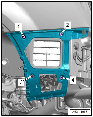
Overview - Bumper Cover Mount
1 - Side Mount
- For the bumper cover
- Removing and Installing. Refer to → Chapter "Side Bumper Cover Mount, Removing and Installing".
2 - Bolt
- Quantity: 4
- Tightening sequence. Refer to → Fig.
3 - Nut
- 2.5 Nm
- Quantity: 2
4 - Center Mount
- For the bumper cover
- Removing and Installing. Refer to → Chapter "Bumper Cover Center Mount, Removing and Installing".
5 - Nut
- 2.5 Nm
- Quantity: 6
6 - Lower Mount
- For the bumper cover
- Removing and Installing. Refer to → Chapter "Bumper Cover Lower Mount, Removing and Installing".
7 - Nut
- 2.5 Nm
- Quantity: 4
Bumper Cover Side Mount - Tightening Specification and Sequence
- Tighten the bolts in the sequence shown -1 to 4- to 3 Nm.
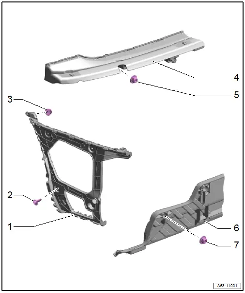
Overview - Impact Member
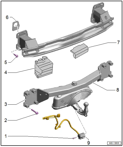
1 - Bolt
- 3.5 Nm
- Quantity: 2
2 - Bolt
- 110 Nm
- Quantity: 4
3 - Impact Member
- For vehicles with a trailer hitch
- Removing and Installing. Refer to → Chapter "Impact Member, Removing and Installing, Vehicles with Trailer Hitch".
4 - Outer Spacer
5 - Bolt
- 110 Nm
- Quantity: 4
6 - Foam Seal
- Replace if damaged
7 - Center Filler Piece
8 - Impact Member
- For vehicles without a trailer hitch
- Removing and Installing. Refer to → Chapter "Impact Member, Removing and Installing, Vehicles without Trailer Hitch".
9 - Socket
- Removing and installing. Refer to → Electrical Equipment General Information; Rep. Gr.96; Trailer Hitch.

