Audi Q7: Impact Member, Removing and Installing
Impact Member, Removing and Installing, Vehicles without Trailer Hitch
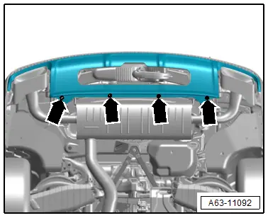
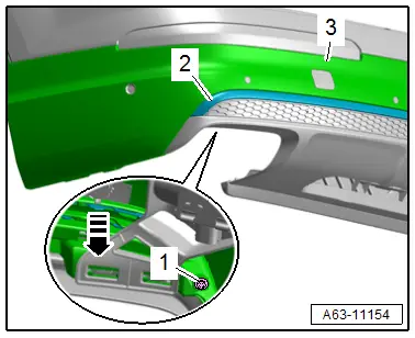
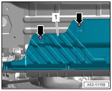
Removing
- Remove the bumper cover. Refer to → Chapter "Bumper Cover, Removing and Installing".
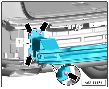
- Remove the bolts -arrows-.
- Remove the impact member -1-.
Installing
Install in reverse order of removal and note the following:
- Check the foam seal for damage.
Tightening Specifications
- Refer to → Chapter "Overview - Impact Member"
Impact Member, Removing and Installing, Vehicles with Trailer Hitch
- To complete the procedure, a second technician is required to be at the following position.
Removing
- Remove the bumper cover. Refer to → Chapter "Bumper Cover, Removing and Installing".
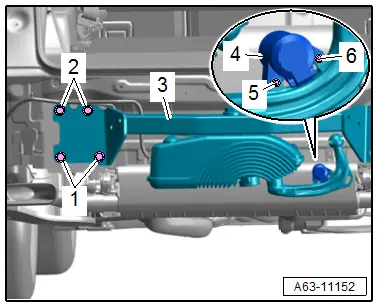
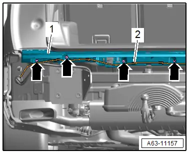
- Remove the bolts -5 and 6- and remove the trailer hitch socket -4-.
- Remove the bolts -1 and 2-.
- Remove the impact member -3- with a second technician.
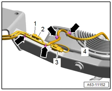
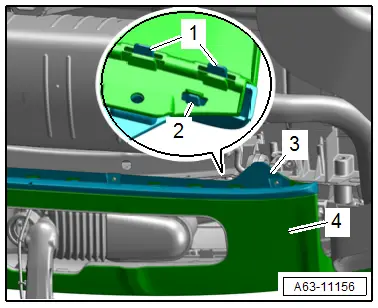
- Disconnect the connectors -1 and 3- and free up the connector -2-.
- Free up the wiring harness -4--arrows-.
Installing
Install in reverse order of removal.
Tightening Specifications
- Refer to → Chapter "Overview - Impact Member"
Attachments, Removing and Installing
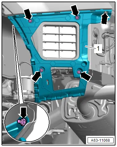
Side Bumper Cover Mount, Removing and Installing
Removing
- Remove the bumper cover. Refer to → Chapter "Bumper Cover, Removing and Installing".
- Remove the bolts and nut -arrows-.
- Remove the side mount -1- for the bumper cover.
Installing
Install in reverse order of removal.
Tightening Specifications
- Refer to → Fig. "Bumper Cover Side Mount - Tightening Specification and Sequence"
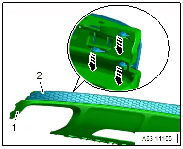
Bumper Cover Lower Section, Removing and Installing
Removing
- Remove the bolts -arrows-.
- If equipped, disconnect the connector -1- on the Rear Lid Opener Control Module -J938-.
- Release the retainers -arrows- and remove the lower section -2- from the bumper cover -3-.
Installing
Install in reverse order of removal and note the following:
- Push the bumper cover lower section into the bumper cover until it clicks into place.
Tightening Specifications
- Refer to → Chapter "Overview - Bumper Cover"
Bumper Cover Lower Section, Removing and Installing, S Line Vehicles
Removing
- Remove the bumper cover trim molding. Refer to → Chapter "Bumper Cover Trim Molding, Removing and Installing, S Line Vehicles".
- Release the retainers -arrows- and remove the lower section -1- from the bumper cover -2-.
Installing
Install in reverse order of removal and note the following:
- Push the bumper cover lower section into the bumper cover until it clicks into place.
Bumper Cover Trim Molding, Removing and Installing, S Line Vehicles
Removing
- Remove the bumper cover. Refer to → Chapter "Bumper Cover, Removing and Installing".
- Remove the bolt -1-.
- Release the catches -arrow- and remove the trim molding -2- from the lower section-3-.
Installing
Install in reverse order of removal and note the following:
- Clip in the trim molding until it engages audibly.
Tightening Specifications
- Refer to → Chapter "Overview - Bumper Cover, S Line Vehicles without High-Voltage System"
Bumper Cover Trim Molding, Removing and Installing, Vehicles with High-Voltage System
Removing
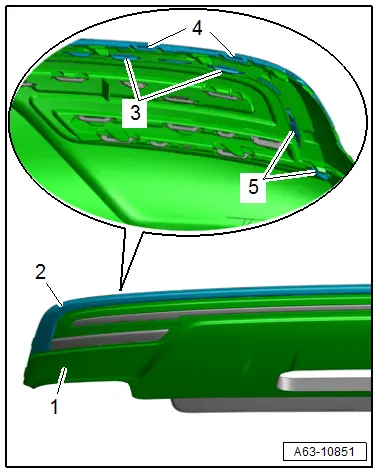
Upper Trim Molding:
- Remove the lower section of the bumper cover. Refer to → Chapter "Bumper Cover Lower Section, Removing and Installing".
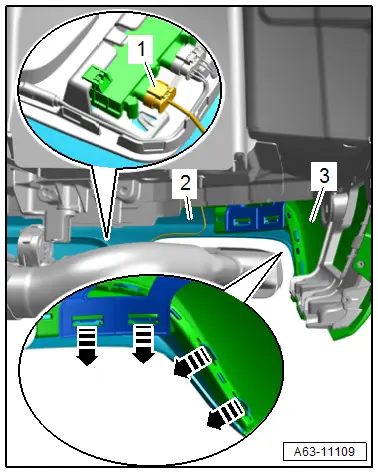
- Release the retainers -3, 4, 5- and remove the trim molding -2- from the lower section -1-.
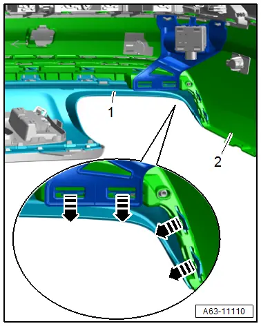
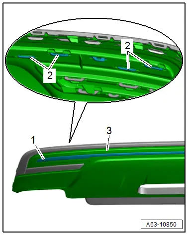
Center Trim Molding:
- Remove the lower section of the bumper cover. Refer to → Chapter "Bumper Cover Lower Section, Removing and Installing".
- Release the retainers -2- and remove the trim molding -1- from the lower section -3-.
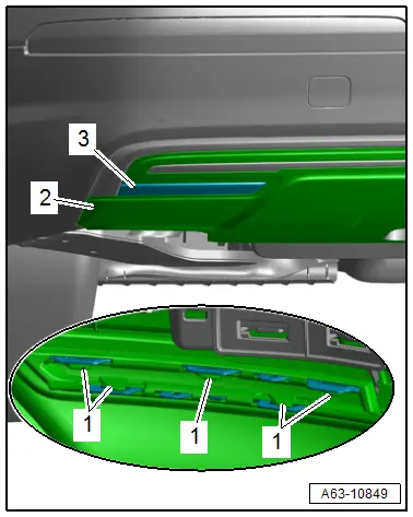
Lower Trim Molding:
- Grip behind the bumper cover, release the retainers -1- and remove the trim molding -3- from the lower section -2-.
Installing
Install in reverse order of removal and note the following:
- Clip in the trim molding until it engages audibly.
Bumper Cover Trim, Removing and Installing
Removing
- Remove the lower section of the bumper cover. Refer to → Chapter "Bumper Cover Lower Section, Removing and Installing, S Line Vehicles".
- Release the catches -arrows- and remove the trim -2- from the bumper cover lower section -1-.
Installing
Install in reverse order of removal.
Spoiler, Removing and Installing
Removing
- Remove the bolts -arrows-.

- Release the catches -1 and 2- and remove spoiler -3- from the bumper cover lower section -4-.
Installing
Install in reverse order of removal.
Tightening Specifications
- Refer to → Chapter "Overview - Bumper Cover"
Bumper Cover Center Mount, Removing and Installing
Removing
- Remove the rear bumper cover. Refer to → Chapter "Bumper Cover, Removing and Installing".
- Free up the wiring harness -2-.
- If equipped, disconnect the connector on the garage door opener control module.
- Remove the nuts -arrows-.
- Remove the center mount -1-.
Installing
Install in reverse order of removal.
Tightening Specifications
- Refer to → Chapter "Overview - Bumper Cover Mount"
Bumper Cover Lower Mount, Removing and Installing
Removing
- Remove the rear bumper cover. Refer to → Chapter "Bumper Cover, Removing and Installing".
- Versions with trailer hitch: remove the impact member. Refer to → Chapter "Impact Member, Removing and Installing, Vehicles with Trailer Hitch".
- Remove the nuts -arrows-.
- Remove the bumper cover mount -1-.
Installing
Install in reverse order of removal.
Tightening Specifications
- Refer to → Chapter "Overview - Bumper Cover Mount"
Special Tools
Special tools and workshop equipment required
- Removal Wedge -T40233-
- Wiring Harness Repair Set - Hot Air Blower -VAS1978/14A-
- Engine Bung Set -VAS6122-
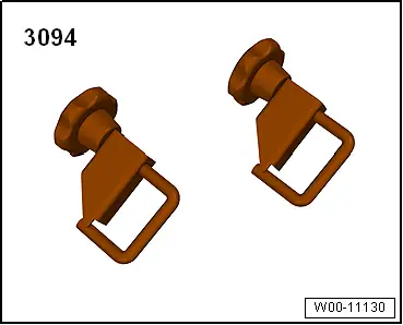
- Hose Clamps - Up To 25 mm -3094-