Audi Q7: Attachments, Removing and Installing
Lock Carrier Cover, Removing and Installing
Special tools and workshop equipment required
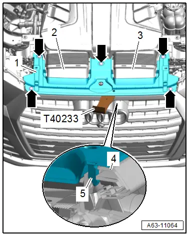
- Removal Wedge -T40233-
Removing
- Remove the hook release lever. Refer to → Chapter "Hook Release Lever, Removing and Installing".
- Remove the headlamp cover. Refer to → Chapter "Headlamp Cover, Removing and Installing".
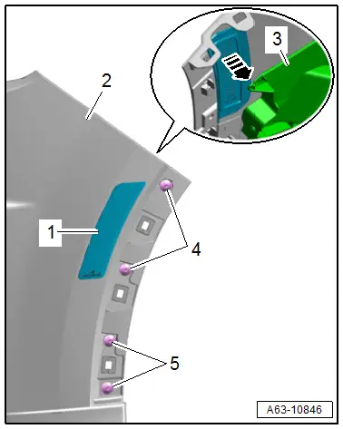
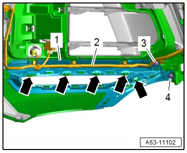
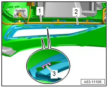
- Remove the expanding clip -arrows-.
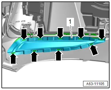
- Release the catches -5- of the lock carrier cover -1- on the radiator grille -4- with the -T40233-.
- Remove the air ducts -2 and 3- from the air filter housing.
- Remove the lock carrier cover.
Installing
Install in reverse order of removal and note the following:
- Push on the lock carrier cover on the radiator grille.
Headlamp Cover, Removing and Installing
Removing
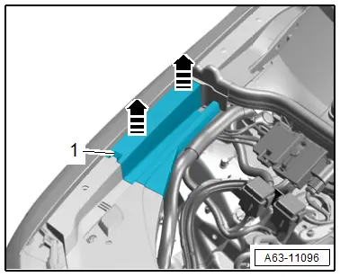
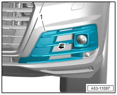
- Right side of the vehicle: remove the cover -1- upward from the catches -arrows- and remove.
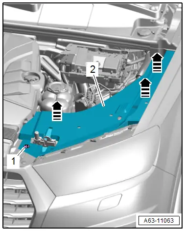
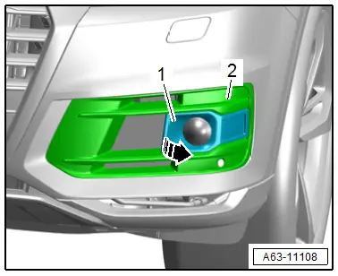
- Turn the quick release -1-.
- Remove the headlamp cover -2- upward from the catches -arrows- and remove.
Installing
Install in reverse order of removal and note the following:
- Check the clips for damage.
- Push in the cover until it engages audibly.
Reflector, Removing and Installing
Special tools and workshop equipment required
- Wiring Harness Repair Set - Hot Air Blower -VAS1978/14A-
- Cleaning Solution -D 009 401 04-
- Applicator -D 009 500 25-
- Bonding Agent -D 366 PR1 A1-
Removing
- Remove the bumper cover. Refer to → Chapter "Bumper Cover, Removing and Installing".
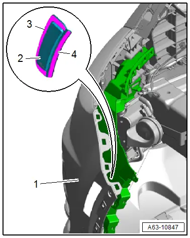
- Remove the bolts -4 and 5-.
- Push the reinforcement -3- as far as possible to the side.
- Carefully warm the reflector -1- using the -VAS1978/14A-.
- Carefully remove the reflector from the bumper cover -2--arrow-.
Installing
Install in reverse order of removal and note the following:
- Clean the adhesive surface using the Cleaning Solution -D 009 401 04-.
- Apply the Bonding Agent -D 366 PR1 A1- to the adhesive surface using the Applicator -D 009 500 25- and let dry.
- Remove the protective film from the adhesive tape -3 and 4-.
- Position the reflector -2- and press it onto the bumper cover -1-.
- Vehicle resting time is at least 3.5 hours at room temperature.
Tightening Specifications
- Refer to → Chapter "Overview - Bumper Cover"
Front Bumper Cover End Plate, Removing and Installing
Removing
- Remove the front noise insulation. Refer to → Chapter "Noise Insulation, Removing and Installing".
- Detach the front section of the front wheel housing liner near the bumper. Refer to → Chapter "Front Wheel Housing Liner, Removing and Installing, Front Section".
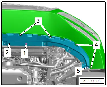
- Remove the bolts -1, 3, 4 and 5-.
- Pull the front bumper cover end panel -2- in the direction of travel toward the rear.
Installing
Install in reverse order of removal.
Tightening Specifications
- Refer to → Chapter "Overview - Bumper Cover"
Impact Guard, Removing and Installing
Removing
- Remove the bumper cover. Refer to → Chapter "Bumper Cover, Removing and Installing".
- Remove the front bumper cover end plate. Refer to → Chapter "Front Bumper Cover End Plate, Removing and Installing".
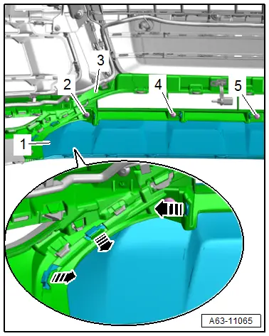
- Remove the bolts -2, 4 and 5-.
- Release the catches -arrows- remove the impact guard -1- toward the front from the bumper cover -3-.
Installing
Install in reverse order of removal.
Tightening Specifications
- Refer to → Chapter "Overview - Bumper Cover"
Air Intake Grille, Removing and Installing
Removing
- Remove the air intake grille -1- downward from the bumper cover -arrow-.
Installing
Install in reverse order of removal.
Air Intake Grille, Removing and Installing, Versions with Adaptive Cruise Control (ACC)
Removing
- Remove the trim -1- from the air intake grille -2--arrow-.
Installing
Install in reverse order of removal.
Side Air Duct, Removing and Installing
Removing
- Remove the impact guard. Refer to → Chapter "Impact Guard, Removing and Installing".
- Remove the bolts -3 and 4-.
- Free up the wiring harness -2-.
- Open the catches -arrows- and remove the side air duct -1-.
Installing
Install in reverse order of removal.
Tightening Specifications
- Refer to → Chapter "Overview - Bumper Cover"
Side Air Duct, Removing and Installing, S Line
Removing
- Remove the front section of the front wheel housing liner. Refer to → Chapter "Front Wheel Housing Liner, Removing and Installing, Front Section".
- Vehicles with side auxiliary cooler: remove the bumper cover. Refer to → Chapter "Bumper Cover, Removing and Installing".
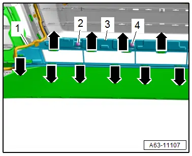
- Open the retainers -arrows- and remove the cover -1-.
- Free up the wiring harness -1-.
- Remove the clips -3- and the side air duct -2-.
Installing
Install in reverse order of removal.
Center Air Duct, Removing and Installing
Removing
- Remove the side air duct. Refer to → Chapter "Side Air Duct, Removing and Installing".
- Free up the wiring harness -1-.
- Remove the bolts -2, 4 and 5-.
- Release the catches -arrows- and remove the air duct in the center -3-.
Installing
Install in reverse order of removal.
Tightening Specifications
- Refer to → Chapter "Overview - Bumper Cover"
Center Air Duct, Removing and Installing, S Line
Removing
- Remove the bumper cover. Refer to → Chapter "Bumper Cover, Removing and Installing".
- Remove the front bumper cover end plate. Refer to → Chapter "Front Bumper Cover End Plate, Removing and Installing".
- Free up the wiring harness -1-.
- Remove the bolts -2 and 4-.
- Release the catches -arrows- and remove the air duct in the center -3-.
Installing
Install in reverse order of removal.
Tightening Specifications
- Refer to → Chapter "Overview - Bumper Cover, S Line"
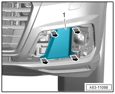
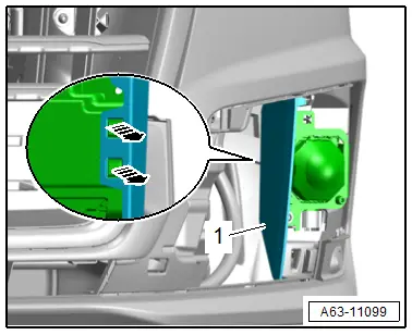
Bumper Cover Lower Section, Removing and Installing
Removing
- Remove the side air duct. Refer to → Chapter "Side Air Duct, Removing and Installing".
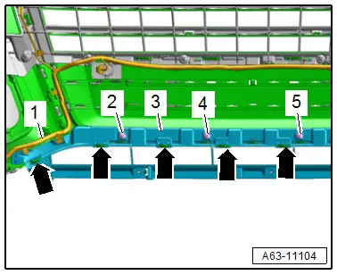
- Remove the bolt -1-.
- Release the retainers -arrows-.
- Remove the bumper cover lower section -3- from the bumper cover -2-.
Installing
Install in reverse order of removal.
Tightening Specifications
- Refer to → Chapter "Overview - Bumper Cover"
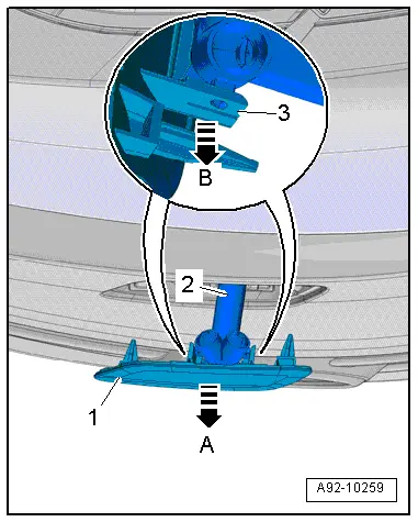
Headlamp Washer System Washer Nozzle Cover, Removing and Installing
Removing
- Pull the spray nozzle telescope -2- out of the bumper cover -arrow A- until it stops.
- Hold the telescope in the extended position with pliers.
- Spread the side bolsters -3- of the cover -1- for the spray nozzle -arrow B- and carefully disengage from the pins and remove.
Installing
Install in reverse order of removal and note the following:
- Press the washer nozzle cover on until it engages audibly.
Air Intake Grille Cap, Removing and Installing
Removing
- Remove the air intake grille. Refer to → Chapter "Air Intake Grille, Removing and Installing".
Air Intake Grille Cap:
- Unlock the catches -arrows- and remove the cap -1- toward the front.
Side Air Intake Grille Cap:
- Unlock the catches -arrows- and remove the cap -1- toward the front.
Installing
Install in reverse order of removal and note the following:
- Press the cover on until it audibly engages.
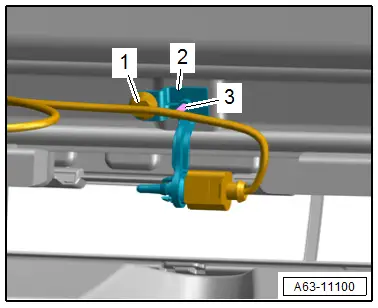
Outside Air Temperature Sensor -G17- Bracket, Removing and Installing
Removing
- Remove the bumper cover. Refer to → Chapter "Bumper Cover, Removing and Installing".
- Remove the outside air temperature sensor. Refer to → Heating, Ventilation and Air Conditioning; Rep. Gr.87; Additional Components for Control and Regulation; Outside Air Temperature SensorG17 Removing and Installing.
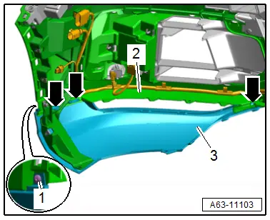
- Free up the wiring harness -1-.
- Remove the expanding pin -3- and the bracket -2-.
Installing
Install in reverse order of removal.
Molded Foam Part, Removing and Installing
- Follow the safety precautions. Refer to → Body Interior; Rep. Gr.00; Safety Precautions; Safety Precautions when Working on Pyrotechnic Components.
Removing
- Remove the front bumper cover. Refer to → Chapter "Bumper Cover, Removing and Installing".
 WARNING
Pyrotechnic components may deploy unintentionally.
Risk of injury.
- Discharge static electricity by briefly touching the door striker.
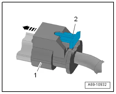
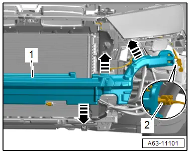
- Disconnect the connector -2- by pulling the connector lock -2- out (refer to → Fig.) and pressing it down.
- Release the tabs -arrows- and remove the molded foam part -1- from the impact member.
Installing
Install in reverse order of removal and note the following:
 CAUTION
Risk of damaging the pressure hose by deforming it.
- Never kink or stretch the pressure hose.
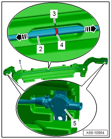
For Pressure Hoses with a Color Marking
- Position the pressure hose -2- at the center of the color mark -4- in the recess at the specified marking -3- in the molded foam part -1-.
For Pressure Hoses without a Color Marking
- Measure out and mark the center of the pressure hose.
- Position the pressure hose equally in both directions -arrows- in the recess in the molded foam part.
Continuation for all Vehicles.
 WARNING
Pyrotechnic components may deploy unintentionally.
Risk of injury.
- Discharge static electricity by briefly touching the door striker.
- Engage the pedestrian protection crash sensor -5- into the molded foam part.
- Attach the connector -1- to the crash sensor until it clicks into place -arrow-.
Connector Lock on Pedestrian Protection Crash Sensor
- Push in the connector lock -2- to secure the connector.